EasyManuals Logo

Casio fx-7400G PLUS Booklet

Casio fx-7400G PLUS
78 pages
To Next Page IconTo Next Page
To Previous Page IconTo Previous Page
Page #42 background imageLoading...
Page #42 background image
– 39 –
M-1 Cam Diagram
Draw the cam diagram of a plate cam with a sliding coupled arm. The cam diagram is created
using cam rotation angles input from a multi-turn potentiometer, and from inputting the displace-
ment volumes of the sliding arm. Data is measured with the EA-100 Data Analyzer.
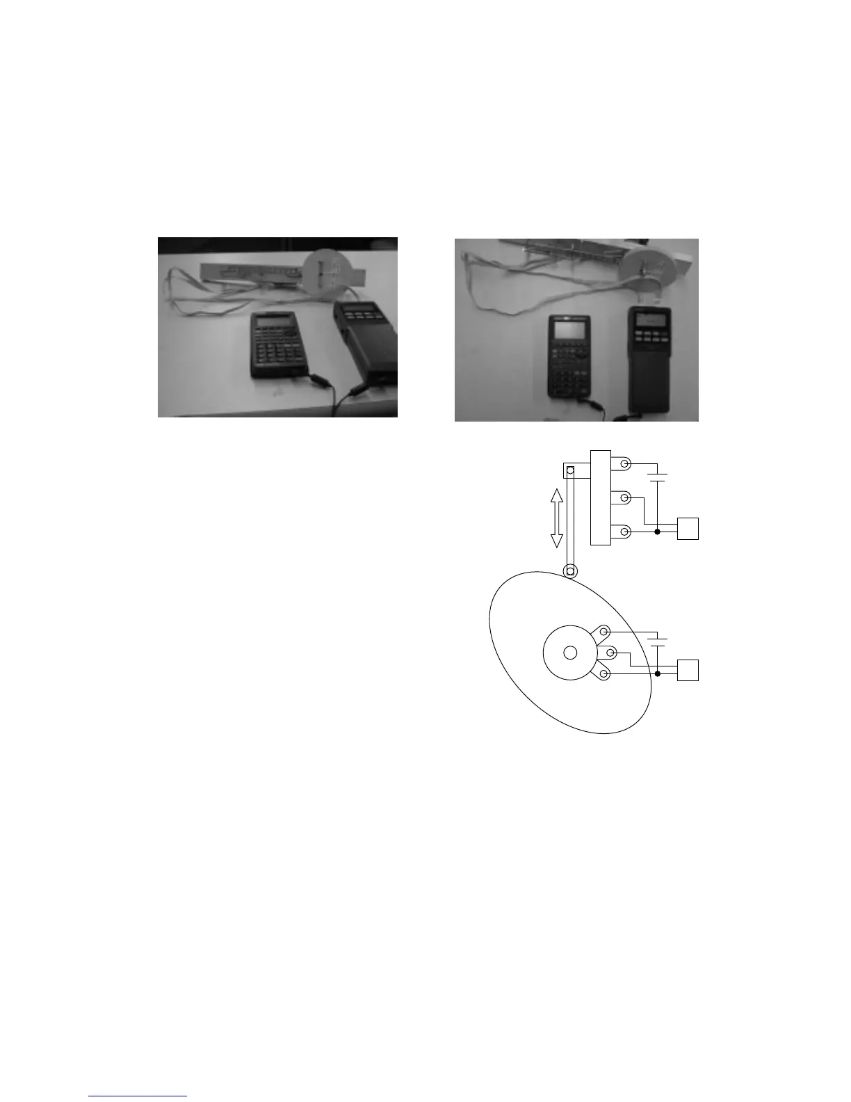
In the above photograph, the displacement of the
sliding arm is input from the sliding volume. The
illustration to the right is the circuit diagram.
Slide resistance is large in the case of sliding
volume, so a strong spring must be used to press
the sliding arm against the cam. Consequently,
micro bearings are used to make the movement of
all parts smoother.
The potentiometer that inputs the cam rotation angle
is a 10-turn type, but a 5-turn or 3-turn type can also
be used.
Pin 2, 6
Pin 2, 6
CH2
EA-100
CH1
EA-100
9V
9V
Sliding arm
Plate cam
Potentiometer
Slide volume

Other manuals for Casio fx-7400G PLUS

Questions and Answers:

Question and Answer IconNeed help?

Do you have a question about the Casio fx-7400G PLUS and is the answer not in the manual?

Casio fx-7400G PLUS Specifications

General IconGeneral
Modelfx-7400G PLUS
CategoryGraphing Calculator
DisplayLCD
Display Lines8
Display Characters21
Memory28 KB
Power SupplyBattery
ProgrammingYes
GraphingYes
Equation SolverYes
Statistical FunctionsYes
ConnectivityNo
BatteryAAA x 4

Related product manuals