– 41 –
M-2 Stepping Motor Excitation Systems
A 2-phase stepping motor with a step angle of 7.5 degrees is connected to a unipolar drive
circuit to observe operation under different excitation systems.
The A phase of the 2-phase stepping motor is connected to DIG-OUT (D0), the B phase is
connected to D1, the A phase is connected to D2, and the B phase is connected to D3 through a
drive circuit, and a digital output buffer is used to drive the motor.
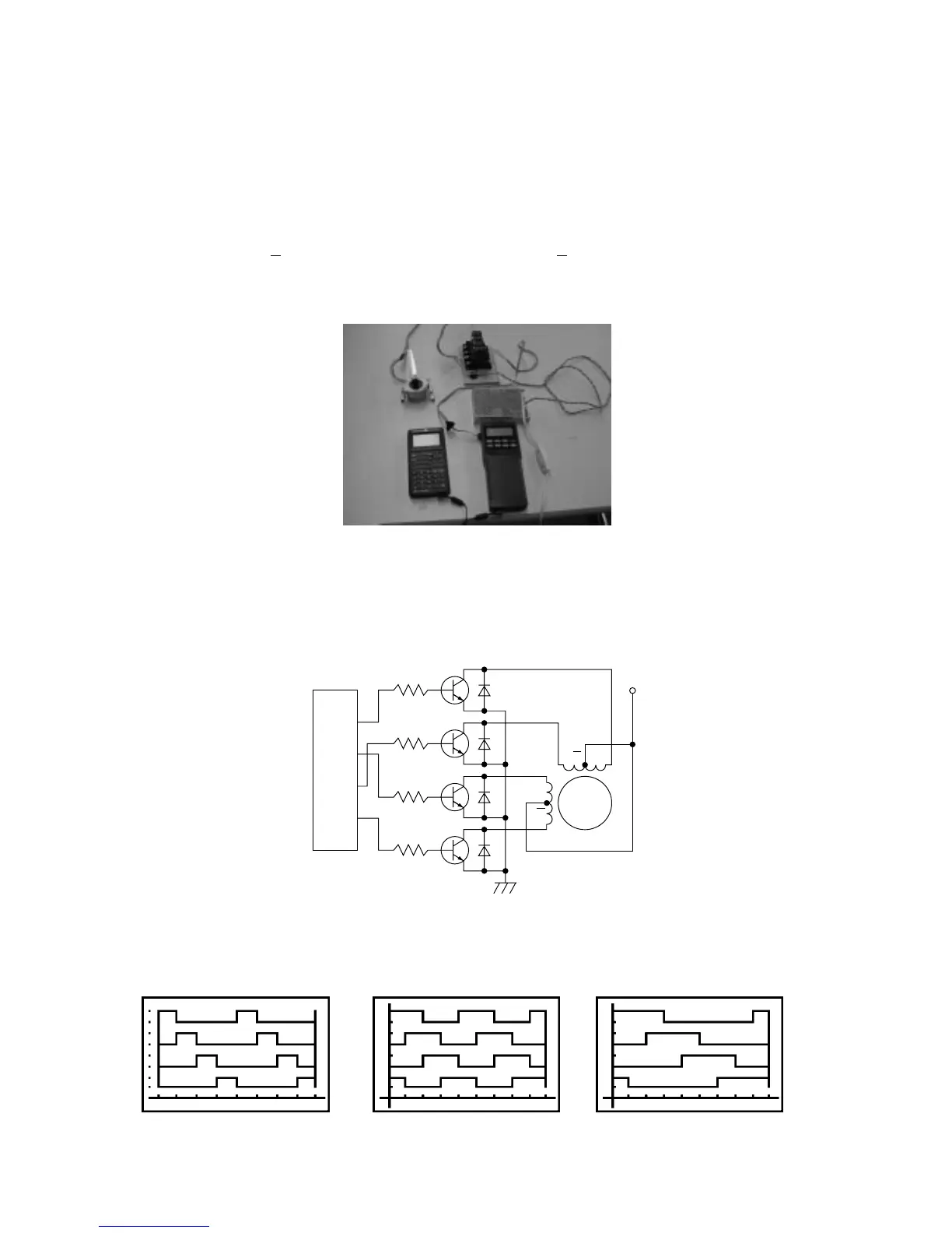
The circuit in the upper photograph uses a solid-state relay (SSR) as the unipolar drive circuit.
The circuit diagram when using darlington transistors as the drive circuit is shown below.
The programs for driving a 2-phase stepping motor and for drawing the charts for each
excitation system are shown below.
3
5
4
6
GND2
R
R
R
R
Tr1
Tr2
Tr3
Tr4
D
I
G
O
U
T
B
B
AA
+
Rotator
1-phase Excitation System
2-phase Excitation System
1-2-phase Excitation System
 Loading...