a. When installed on the controller, set the system STOP switch to ‘STOP’ and the ON/OFF switch to
‘OFF’. This will completely isolate the controller.
b. Ensure power is removed from the crane or machine motors. This is normally done by opening the
disconnects for the motors at the motor control panels.
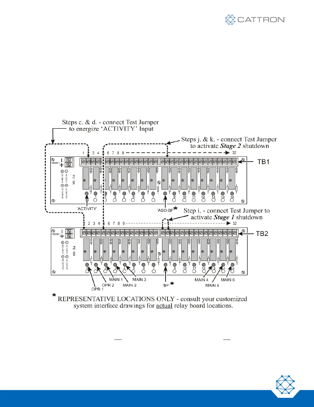
c. Referring to Figure 16, open the receiver/decoder door and touch one end of a Test Jumper to
TB2 – Terminal 1.
Touch the other end of the test jumper to TB1 – Terminal 2.
This will energize the ACTIVITY Input. The system status display will post a ‘system shutdown’
bulletin because the mainline was energized without command.
Figure 16: Input and Output Relay Interface Boards – ASO Test Points
Apply power to the controller (set to ‘ON’) and activate a non-motion function, such as a horn, siren or
light. The decoder should not operate, and the commanded action should not occur.
d. Set the controller power to ‘OFF’.