Recommended Safety Rules for Portable Remote Controlled (PRC) Cranes is provided in Appendix II –
Recommended Safety Rules for Portable Remote Controlled (PRC) Cranes of this manual.
1. Before lifting any loads, carry out the following:
a. Ensure the address code and frequency of your remote controller exactly matches the address
code and frequency of the target crane to be operated. The address and frequency assigned to
your controller is recorded (1) on the front page of the manual supplied with the controller, and (2)
on a serial tag located inside the battery door. The address and frequency of the MP96 Series
receiver/decoder is recorded (1) on the front page of the manual supplied with the portable remote
control system, and (2) on a label located on the outside of the electronics chassis (i.e., Gold Box)
inside the receiver/decoder cabinet. If a controller having the wrong address code and frequency is
selected, the target crane will not operate. However, other equipment located at, around or nearby
your facility may become operational.
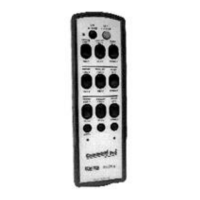
Note: If you are not familiar with the controls and indicators on your controller, please refer to
the ‘Controls and Indicators’ section of the manual supplied with your controller.
Some controllers have two Power ON/OFF Switches. These may be a combination of
either a key, toggle, rotary or pull/‘ON’-push/‘OFF’ switch. Both of these Power ON/OFF
Switches must be set to ‘ON’ for power to be applied to the controller.
b. Set the controller’s Power ON/OFF Switch(es) to the ‘ON’ position. When transmitting with a good
battery, two short ‘beeps’ will be heard immediately after the Power ON/OFF Switch is set to ‘ON’
and a green TRANSMIT LED will ‘flash’ rhythmically. When the battery starts to go low, the green
LED changes to a red or yellow (depending on the type of controller) LOW BATTERY LED which
‘flashes’ continuously. This means you should change or recharge the battery pack as soon as
possible.
c. When installed, depress the ALARM/RESET pushbutton switch located in the center of the
controller’s Push-To-Operate (PTO) Bar (this is normally an optional function that sounds the
equipment alarm or horn and resets the main power contactor).
d. Check each function independently to be sure that equipment is responding correctly.
e. Where a limit switch is provided, you should check the limit switch at the beginning of each shift as
defined by your plant operating procedures.
f. Check Range Limiting if used – refer to Appendix I – R2HN Receiver of this manual.
g. Check STOP operation.
h. Check Brake operation.
2. Report all defective or missing safety equipment, mechanical or electrical defects to your supervisor
without delay. Do not continue operation until fully repaired.
3. When raising or lowering a load, proceed slowly and make certain the load is under control.
4. When lifting maximum load, you should test the brakes by raising the load a few inches from the floor. If
the brakes will not hold, the load shall be immediately lowered and not moved until brakes are adjusted or
repaired.
5. Center the Trolley directly over the load before starting to hoist.