GridScan/Pro English
8 © CEDES | V 1.0
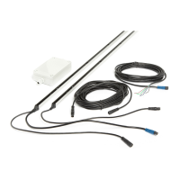
3. Mount the emitter edge across from the receiver edge. If the receiver is mounted in the guiding rail the emitter
should be mounted in the guiding rail opposite the receiver.
Important: Make sure the optical elements are facing each other (Chapter 5.3).
4. Connect the emitter with the receiver edge using the synchronization cable.
5. Plug the connection cable into the blue plug on the receiver edge and connect it to the door controller (Chapter 8).
8. Electrical connection
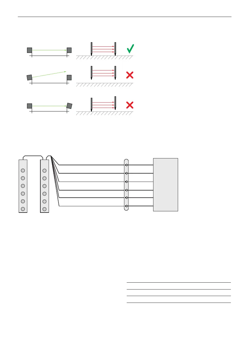
Figure 11: Connection diagram
Important: Any unconnected (not used) wire must be separated and isolated.
8.1 Outputs
When an object enters the safeguarded area (OBJECT DETECTED) the GridScan/Pro output changes after response time
t2 (Chapter 9). When the object leaves the safeguarded area (NO OBJECT) the GridScan/Pro output switches back after
release time t3.
8.1.1 Changing the output logic
Output 1 logic is set using the gray wire. The logic will
be defined by the power-up sequence. After the power-
up the logic will not change until the next power-up
is made. The default logic is LO (light-on) (used in the
timing diagram). The output logic is LO if the gray wire is
connected to GND (0 V). Connecting the gray wire to USP
(10 ... 30 VDC) changes the output logic to DO (dark-on).
If the gray wire is not connected (floated), the output logic
changes to the FSS signal.
5
2
4
3
1
6
Selectable output logic
Test input*
Output 1 (PNP/NPN and FSS)
U
SP
GND (0 V)
Not used or Output 2 (PNP/NPN)
Door
controller
Tx Rx
M8, 6-pin
brown
black
gray
white
cable
* If FSS output is
selected white wire needs
to be connected to U
SP
or test signal
blue
green
Tx // Rx
Tx not // Rx
Tx not // Rx
Gray wire Output 1 Logic
Connected to GND (0 V) Push-Pull LO
Connected to USP Push-Pull DO
Not connected (floated) FSS
Table 1: Output 1 logic selection table