CENTRALINE I/O MODULES – INSTALLATION & COMMISSIONING INSTRUCTIONS
47 EN1Z-0973GE51 R0119
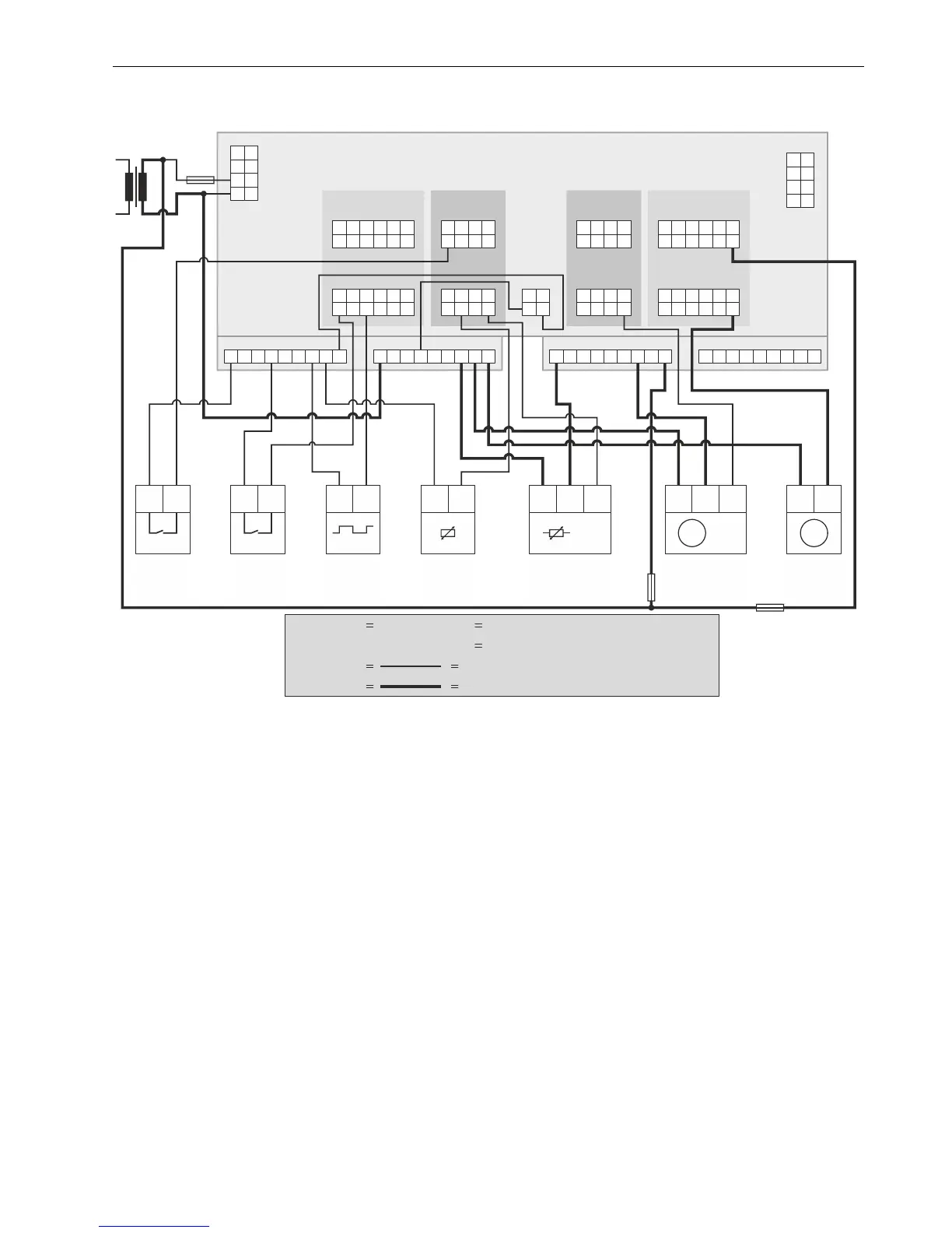
Connection Example
CLIOP830A Mixed I/O Module
2 21
DRY
CONTACT
1: GND
2: SIGNAL
DRY
CONTACT
1: GND
2: SIGNAL
21 1
CTIVE
SENSOR
1: GND (24V 0)
2: 24V POWER
3: 0...10 VDC
~
~
2
3 3
1
0...10 VDC 0...10 VDC
M
1 2
M
1 2
XS830 OPT. AUX. TERM. MODULE XS830
F1
F4
1 2
74
24
V~0
73
72
71
24
V~
COM
B
COM
A
78
24
~0
77
76
75
24
V~
COM
B
COM
A
41 42
B10 B11 B12
AI5
AI1
AI6
AI2
AI7
AI3
I8
I4
O5
O1
O6
O2
O7
O3
O8
O4
IN1
NO1
IN2
NO2
IN3
NO3
IN4
NO4
IN5
NO5
IN6
NO6
B7 B8 B9
7 8 9 10
11 12 17
13
18
14
19
15
20
16
25
21
26
22
27
23
28
24
35
29
36
30
37
31
38
32
39
33
40
34
B1 B2 B3 B4
B5
B6
1 2
3
4
5
6
G1 G2
A7
7B7 B7
A8
8B8 B8A9
9B9 B9
A1 A1B1 B1A2 A2B2 B2
A3 A3B3 B3
A4 A4B4 B4
A5 A5B5 B5A6 A6B6 B6
TOTALIZER
1: GND
2: SIGNAL
NTC20kOHM
SENSOR
1: GND
2: SIGNAL
24V
1: GND (24V 0)
2: 24V POWER
3: 0...10 VDC
~ DRIVE with
0...10V SIGNAL
~
~
DCA
1: 24V 0
2: 24V
~
~
MIN. 0.75 mm
2
MIN. 1.5 mm - or less, as per F2, F4
2
THIN LINES
F4
F1 F2
LEGEND:
THICK LINES
MAX. 3 A
MAX. 4 A
MAX. 12 A
F2
(GND 24 VAC)
BINARY INPUTS
NALOG INPUTS
NALOG OUTPUTS 24V RELAYS
(24 VAC)(GND)
Fig. 61. CLIOP830A Connection example
For fusing specifications see section "Fusing Specifications" on page 8. For internal connections of auxiliary terminal modules,
see section “XS830 Auxiliary Terminal Package” and section “XS831 Auxiliary Terminal Package” on page 49.
 Loading...