page 44 www.centsys.com
COMMISSIONINGSECTION 8
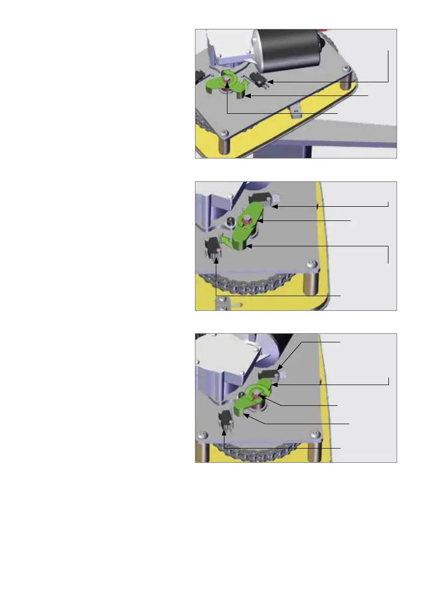
To set the closed limit position,
loosen the clamping bolt that is
holding the plastic arms to the shaft
and gently rotate the plastic arm
until the switch clicks. The closed
limit is now set and can be adjusted
later.
FIGURE 55
Limit Switch 1
(Closing)
Limit
Arm 1
Limit Clamping
Bolt
To set the open limit of the gate,
the motor will need to be connected
directly to a battery and the gate
moved to the desired open position.
Once again take care that the plastic
limit arms do not come into contact
with other components of the
operator. Rotate the second plastic
arm until Limit Switch 2 clicks. The
open limit has now been set and can
be adjusted later.
FIGURE 56
Gently tighten the fastener that
clamps the plastic limit arms so that
they are held in place.
FIGURE 57
Limit Switch 1
(Closing)
Limit Switch 1
(Closing)
Limit Arm 1
in Position
(Closing)
Limit Arm 1
in Position
(Closing)
Limit Clamping
Bolt
Limit Arm 2
(Opening)
Limit Arm 2
in postion
(Opening)
Limit Switch 2
(Opening)
Limit Switch 2
(Opening)
Fit the motor wires back into the terminal block and run a gate cycle using the CP77
controlcard.Theopenandclosedlimitsmayneedtobenelyadjustedinorderto
account for the ramp-up and ramp-down of the control card when triggered.
With reference to Figure 55 and in an instance where the Drive Arm rotates clockwise
when the gate closes, Limit Switch 2 will be the closed limit and Limit Switch 1 will be
the open limit. The user will need to swop the wiring of these two limit switches on the
terminal block.