MANUALPC-2010 CHAPTER II – INSTALLATION Page 6
CHAPTER II - INSTALLATION
SAFETY NOTICE
See important safety information on the first page of the
manual.
UNPACKING
Immediately upon receipt of your shipment, check the shipping
carton carefully for damage and report any damage directly to
the shipping company. Please report any shortage
immediately to the factory.
Before opening the carton, check the outside label and verify
the model number, voltage, tee size and feed mode. Unpack
the carton carefully and accounting for any of small parts such
as PVC fittings.
The controller carton should include the following:
- Controller Cabinet,
- Sensors as required for selected model,
- Instruction Manual and Warranty Card,
- Installation Report to be mailed back to factory upon
completion of installation,
- Bypass Line Assembly (Optional).
INSTALLATION REPORT
T
he Installation Report is a triplicate form designed to assure
warranty coverage, technical updates and factory support.
1. White copy: to mail back to factory.
2. Pink copy: to Facilities Manager.
3. Yellow copy: to Qualified Dealer.
Upon completion of installation, it must be filled out and signed
by the Qualified Dealer and by the facilities manager.
TECHNICAL SUPPORT
P
lease take your time to read this detailed Instruction Manual
to insure proper installation and operation. If you need further
technical assistance, you can contact your Qualified
CHEMTROL® Representative, call our Technical Department
toll free at 800-621-2279 or e-mail us at
chemtrol@sbcontrol.com.
PRINCIPLE OF INSTALLATION
C
HEMTROL® PC constitutes an integrated command center
for complete monitoring and control of all water treatment
operations, including chemistry, filtration, heating recirculation
pump and water level.
All information provided by the sensors is processed by the
microprocessor on the Mother Board and displayed on the
Main display screen. Command signals are then sent to the
different control outputs on the Power Board (see
ELECTRICAL below).
The schematic of installation in Figure 5 shows the principle of
installation with all options installed. Figure 11 show the details
of installation for the bypass line and sensor cell assembly.
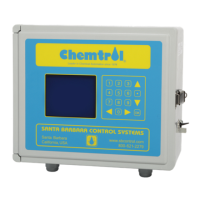
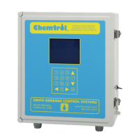
CONTROLLER CABINET
C
HEMTROL® PC controllers are contained in a rain proof and
splash proof NEMA Type 3 cabinets.
For ease of installation, there are two external mounting ears
on the top of the cabinet.
All the electronic and electrical components are mounted
inside the cabinet on two separate PC Boards, the Mother
Board and the Power Board. Outlets are provided on the
bottom of the cabinet for ½" conduits connectors.
LOCATION
M
ount the cabinet on a wall in a secure location:
- More than 10' (3 m) away from the water edge to comply
with electrical code requirements,
- Within 10' (3 m) of the main recirculation line or of the
bypass line - unless special extension cables are used for
the sensors (see Sensor Cables),
- Not exposed to direct sunlight as the LCD display screen will
darken at high temperature,
- Easily accessible to maintenance personnel,
- If possible, in a separate or well-ventilated room as far away
as possible from corrosive chemicals and storage tanks,
- At a safe distance from power transformers, pump motors or
high voltage power lines,
- Safe from unauthorized access or vandalism


 To Next Page