MANUALPC-2010 CHAPTER II – INSTALLATION Page 13
PLUMBING
This section covers the installation of the sensors and the
connection of the chemical feeders or control valves.
All chemical injection should be done on the return line, i.e.
downstream of the sensors and pool equipment, as explained
in the Chemical Feeders section.
Installation of Sensors
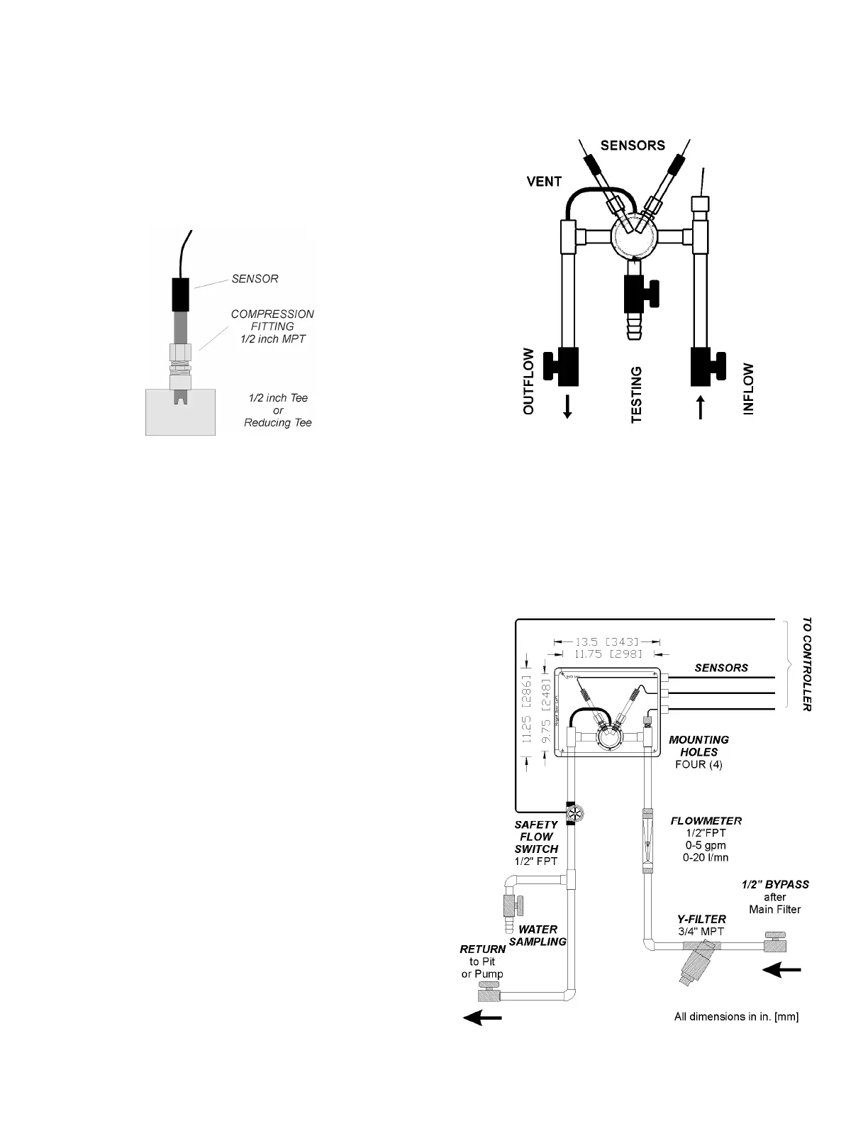
Figure 9 - Sensor Installation
The CHEMTROL® PC controllers use up to nine different
sensors for measurement of water chemistry, temperature,
flow rate, pressure and water level:
- amperometric sensor for Free Chlorine,
- potentiometric sensors for pH and ORP,
- thermistor for temperature,
- conductivity sensor for Total Dissolved Solids,
- Hall effect pulse generator for flow rate,
- piezoelectric sensors for influent and effluent pressures,
- electro-optical water level sensor.
The first five sensors measure water chemistry (Free Chlorine,
ORP, pH, conductivity and temperature). These can be
mounted directly on a 2-inch main recirculation line using PVC
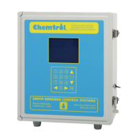
reducing tees Figure 9). On larger diameter lines, they must
be mounted on a ½-inch bypass line - using a Sensor Cell
Cabinet (Figure 11).
In-line Installation (2" Pipe)
O
n smaller installations (2 “ pipe diameter), the sensors can be
mounted directly on the main recirculation line between the
strainer and the pump (Figure 9).
Use only 2x2x½ in. SST reducing tees without reducers. Do
not install the sensors near an elbow or a constriction where
there might be excessive turbulence.
Install the tees on the suction side of the pump and make sure
that the tip of the sensor is oriented downward - as shown in
Figure 9 - to avoid formation of air pockets near the tip. The
sensors should be readily accessible for servicing but not
exposed to physical damage.
After inserting the sensor, be careful not to overtighten the
compression fitting as it can crush the small glass tube inside
the sensor. Make it finger tight (no wrench).
Flow Cell Assembly
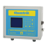
Figure 10 - Flow cell Assembly
For ease of installation and maintenance, the sensors should
be mounted on the Flow Cell Assembly, as show above. It
includes a sensor cell with an air vent and a clear cover, two
compression fittings for the ORP and pH sensors, a water
sampling tap and two ball valves for controlling the water flow
in and out.
Sensor Cell Cabinet (Option)
Figure 11 - Sensor Cell Cabinet (Option)


 To Next Page