MANUALPC-2010 CHAPTER II – INSTALLATION Page 19
PRESSURE TRANSDUCERS
The pressure sensors are CHEMTROL® Series 1200
transducers (Figure 22) with a 1/4-18 NPT thread connection
rated at -15 to 45 psi (-1 to 3 bar).
For differential pressure monitoring, a transducer should be
installed on the intake (influent) side of the filter or bank of
filters and another one on the return (effluent) side.
Transducer Connections
C
onnect the leads from the sensors to the Terminal Barrier
strip TB2 as indicated on the Mother Board Schematic (Error!
Reference source not found.). For calibration, enter a factor
of 4.3 through the PUMP Submenu 6.2.1 (Page 41).
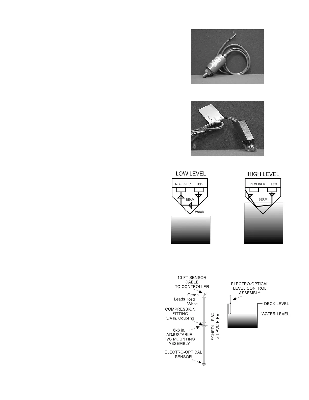
WATER LEVEL SENSOR
The water level in the pool can be automatically maintained
with a fill valve controlled by the water level sensor. The
sensor is an ELS-1100 Series electro-optical sensor with a 1/4"
NPT thread (Figure 23). Having no moving parts, it is simpler
and more reliable than mechanical systems.
The optical sensor uses the reflection of an LED light beam
inside a prism to determine the position of the water level
(Figure 24). With no liquid present, the light beam from the
LED is reflected within the prism to the receiver. When the
liquid level reaches the prism, the index of refraction is
changed and the beam is cannot be detected by the receiver.
Installation
Locate the sensor in a convenient location in the pool, surge pit
or water tank as shown on Figure 25. Wire the fill valve to the
Level Fill relay.
Connect the leads from the sensor to the Terminal Barrier strip
TB1 as indicated on the Mother Board Schematic (Error!
Reference source not found.).
Maintenance
The surface of the prism should always be kept clean and
should be positioned at least 2" (cm) away from reflective
surfaces.
Figure 22 - Pressure Transducer
Figure 23 - Optical Level Sensor
Figure 24 - Optical Beam Path
Figure 25 - Water Level Assembly
 Loading...