MANUALPC-2012 Page 3
LIST OF FIGURES
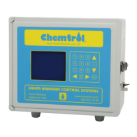
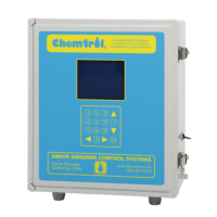
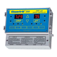
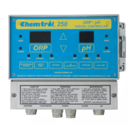
Figure 1 - Models Comparision Chart.......................................2
Figure 2 - Equilibrium of Free Chlorine.....................................3
Figure 3 - Control Panel and Main Screen ...............................4
Figure 4 - Remote Computer....................................................4
Figure 5 – Installation Schematics............................................7
Figure 6 - Mother Board ........... Error! Bookmark not defined.
Figure 9 - Power Board ............Error! Bookmark not defined.
Figure 10 - Multiplex Connections ..........................................11
Figure 11 - Installation of Optional Boards .............................12
Figure 12 - 4-20 mA Converter Board ....................................12
Figure 13 - Sensor Installation................................................13
Figure 14 - Flow cell Assembly .
..........................................13
Figure 15 - Sensor Cell Cabinet (Option)............................13
Figure 16 - PPM Sensor Flow Cell .........................................15
Figure 17 - PPM Sensor Package ..........................................15
Figure 18 - ORP and pH Sensors...........................................16
Figure 19 - Temperature Sensor ...........................................17
Figure 20 - Conductivity Sensor .............................................17
Figure 21 - Flow Sensor Installation .......................................18
Figure 22 - Model 2536 Flow Sensor .....................................18
Figure 23 - Model 2540 Flow Sensor .....................................18
Figure 24 - Saddle for FS2536 ...............................................18
Figure 25 - Saddle for FS 2540 ..............................................18
Figure 26 - Pressure Transducer............................................19
Figure 27 - Optical Level Sensor............................................19
Figure 28 - Optical Beam Path...............................................19
Figure 29 - Water Level Assembly .........................................19
Figure 30 - Erosion Feeder Control........................................20
Figure 31 - Single Filter Backwash......................................... 21
Figure 32 - Multiple Filter Backwash ......................................21
Figure 33 - On-screen Data Log.............................................28
Figure 34 - Proportional Feed Rate........................................48
Figure 35 - CHEMCOM
™
Program Menu..............................51
Figure 36 - CHEMCOM
™
System Setup............................... 51
Figure 37 - CHEMCOM
™
Facility Menu ................................51
Figure 38 - CHEMCOM
™
Facility Selection ..........................52
Figure 39 - CHEMCOM
™
Secondary Units ........................... 52
Figure 40 - CHEMCOM
™
Remote Operation Screen............52
Figure 41 - CHEMCOM
™
Automatic Scanning .....................53
Figure 42 - CHEMCOM
™
Scan Facilities .............................53
Figure 43 - CHEMCOM
™
Manual Scanning..........................53
Figure 44 - CHEMCOM
™
Recent Scans............................... 53
Figure 45 - CHEMCOM
™
Data Display.................................54
Figure 46 - CHEMCOM
™
Text Data Display .........................54
Figure 47 - CHEMCOM
™
Graphic Data Display....................54
Figure 48 - PORTA-PROBE
TM
Portable Tester......................58
Figure 49 - pH / mV Scale......................................................58