MANUALPC-2010 CHAPTER II – INSTALLATION Page 9
Remote Alarm
The remote alarm is a 5A DPDT relay located on the upper
right corner of the Power Board. The remote alarm relay can
be set for dry or hot contacts, or for any external signal.
To avoid damaging the Power Board, make sure to use the
right type of contacts. Call your dealer or the factory if you are
not sure.
With hot contacts, the controller powers the alarm with 110 or
230V, depending on the setting of the input voltage of the
controller (see preceding page). Connect the leads to the
alarm to the Normally Open contacts (NO1 and NO2) on the
terminal strip located next to the alarm relay.
For an external power source, wire the input power to the
terminals marked NC1 and NC2. Wire the remote alarm to the
normally open contact (NO1 and NO2). The alarm voltage will
be the same as the external power source.
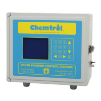
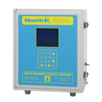
Mother Board
T
he Mother Board is mounted directly behind the face panel of
the controller and contains all the low voltage circuitry including
the microprocessor and program chips, the LCD display and
the keyboard pad. It is also used to connect all the sensor
inputs.
The key electronic components are the microprocessor and the
programmable chips for Program, Display and Memory. The
program chips are located in the center at the very top of the
board. They can be replaced for upgrading of the software
program, which should be done only by an experienced
technician.
Sensor Connections
A
ll sensor connections are on the Terminal Barrier strips on the
Mother Board, as shown on Error! Reference source not
found.. The pH and ORP sensors are connected externally to
the bulkhead BNC connectors on the left side of the cabinet.
The temperature sensor has two leads, black and red. The
combined conductivity/temperature sensor has four leads:
white, green, red and black. Connect all leads as shown on
the Mother Board schematic (Error! Reference source not
found.).
The color coding for the connections are as follows.
TB1 - Level control sensor and
blade-type flow switch (PC3) or high alarm sensor (PC6)
5 = Low White wire from level sensor
4 = Ground
3 = Flow switch NO f/s wire or white wire high alarm
2 = Ground Black wires
1 = +5vdc Red wires from level sensors
TB2 - Pressure transducer
4 = In White wire from influent transducer
3 = Out White wire from effluent transducer
2 = Ground Black wire
1 = 24vdc Red wire from transducers
TB3 - Bypass line flow pulser
3 = +5VDC Red wire
2 = Signal White wire
1 = Ground Black wire
TB4 - Main flow pulser (Signet)
3 = + Black
2 = Signal Red
1 = Ground Shield
TB5 - Temp & TDS, pH, ORP
8 = TDS Black
7 = TDS Red
6 = Temperature White Red
5 = Temperature Green Black
4 = pH Shield
3 = pH Signal
2 = ORP Shield
1 = ORP Signal
TB6 - RS-485 Communications
Connect to A and B only, for multiple serial installations,
using Host/Slave configurations (see Remote
Communications below).
TB7 - RS-232 Communications
5 = Green
4 = Brown
3 = Black
2 = White
1 = Red
Buzzer
The buzzer is located near the bottom of the Mother Board, as
shown on Error! Reference source not found.. It can be
turned on for specific alarm conditions through the software
program or for all alarms using the Audio Alarm Submenu
8.2.1 (see page 27).
Display Brightness