MANUALPC-2010 CHAPTER II – INSTALLATION Page 18
FLOW SENSOR
Flow Sensor Location
Always install the flow sensor as far away as possible from
obstructions that can affect the flow profile around the sensor.
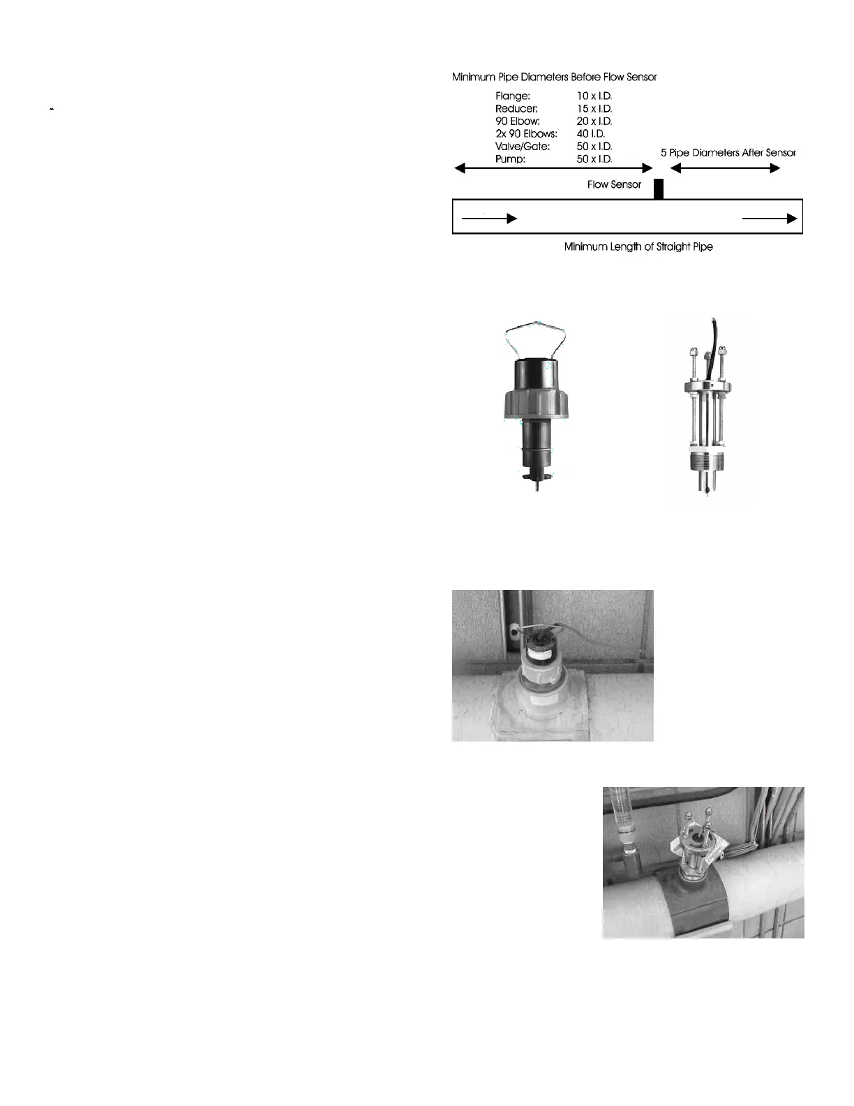
Figure 17 shows manufacturer guidelines for minimum lengths
of straight pipe before and after the sensor. For best results,
respect these guidelines as much as possible.
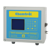
Depending on pipe diameter, three different models of sensors
are used for flow monitoring:
- Model 2536-P0 for diameters from 2 to 4 in (50 to 100 mm)
(Figure 18),
- Model 2536-P1 for diameters from 5 to 8 in (100 to 200 mm)
(Figure 18),
- Model 2540 for lines over 10 in. (250 mm) in diameter
(Figure 19).
The rotor shaft should be inserted at least 10% of the pipe
diameter into the water. The sensors are paddle wheel-type,
Hall effect generators with a true square wave. They are rated
at 200 psi (14 bar) at 68
O
F (20
O
C). The signal can be
transmitted up to 1000 feet (300 m) without distortion.
Follow manufacturer instructions carefully and do not install
while the line is under pressure.
Flow Sensor Saddles
Saddle assemblies for flow sensors are available in 2, 4, 6 and
8 in. diameter (see Figure 20 and Error! Reference source
not found.). For larger sizes, call the factory for special order.
Flow Sensor Connections
Connect the three leads from the sensor to the Terminal
Barrier strip TB 4 as indicated on the Mother Board Schematic
(Error! Reference source not found.).
CAUTION: A 24 V DC signal is used for signal generation.
Reversing the wires may cause damage to the sensor and to
the microprocessor.
Enter the calibration K-factor in pulses per unit of volume
flow (gpm or l/m) for the specific pipe diameter and thickness,
as discussed in Chapter IV - Operation (Page 42).
Figure 17 - Flow Sensor Installation
Figure 18 - Model 2536 Flow Sensor
Figure 19 - Model 2540 Flow Sensor
Figure 20 - Saddle for FS2536
Figure 21 - Saddle for FS 2540


 To Next Page