MANUALPC-2010 CHAPTER II – INSTALLATION Page 12
4-20 mA Converter Boards
The 4-20 mA Converter Boards are two optional piggyback
boards. They convert the digital outputs of the controller
(sensor or control outputs) into analog signals that can be used
by analog monitoring and control equipment.
The two boards are identical and are normally installed at the
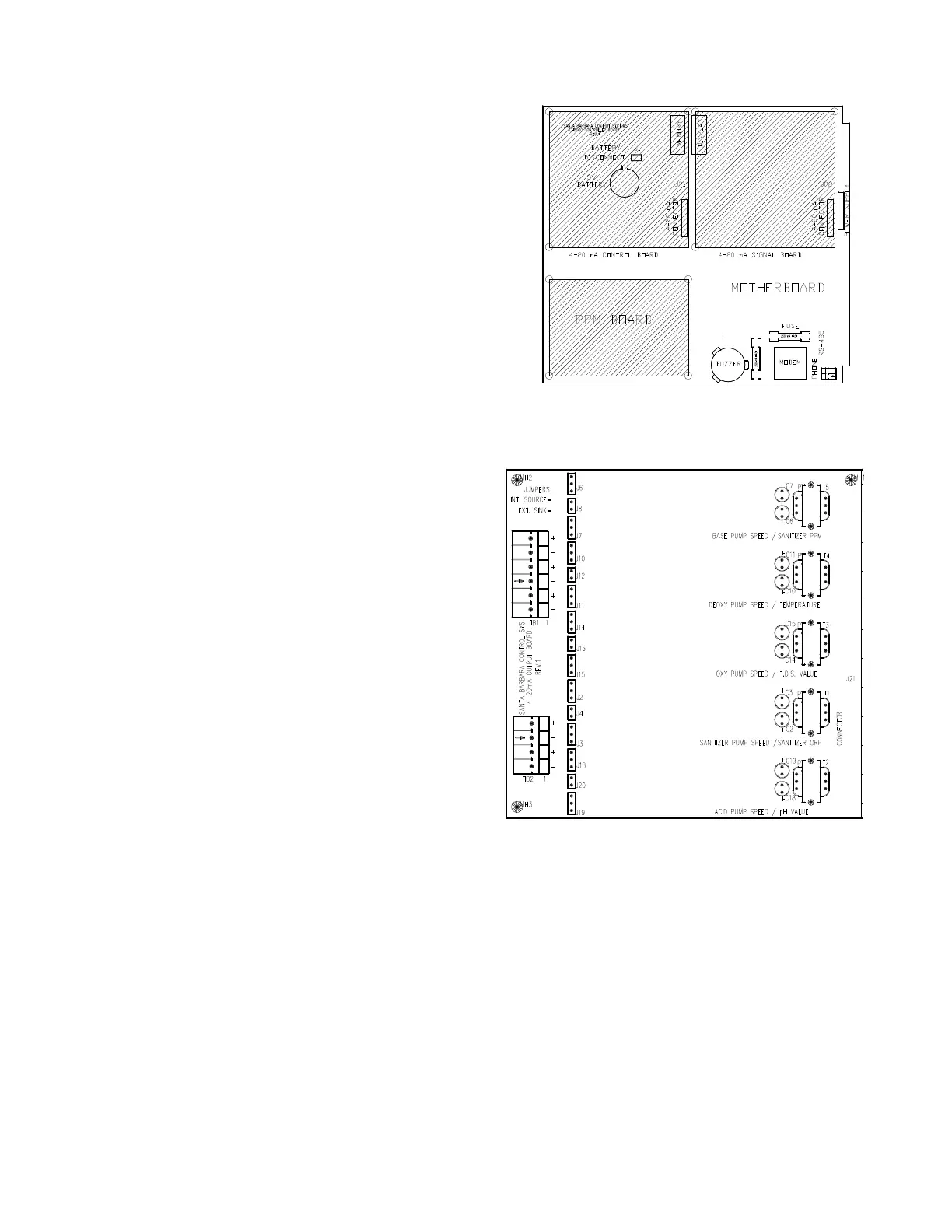
factory on the motherboard before shipping, as shown in
(Figure 7). The location on the motherboard determines the
function, i.e. sensor signal or control outputs. Either one of the
boards or both can be installed, depending on requirements.
If the boards are installed properly, the controller software
automatically shows the 4-20 mA menu line in the Submenu
8.3 - Communications.
Field Installation
F
or field installation, turn off all power to the controller.
Position the converter board on top of the motherboard as
shown on Figure 7. Press the electrical connector J21 into the
socket of the motherboard marked JP1 (or JP2 depending on
option) and the three plastic standoffs fittings into the three
corresponding holes on the motherboard.
4-20 mA Connections
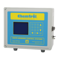
Figure 8 shows the connections for each Converter Board.
Determine the type of signal required by the host system.
There are two types of signals used in 4-20mA
communications, Internal source or external sink. Each
communication channel has four sets of jumpers that must be
shunted to the proper setting. (Please note that the factory
settings are generally for internal source).
The 4-20mA output signals from the board are located on the
terminal boards marked TB1 and TB2. Each channel has a +
and - indication corresponding to the markings on the board.
The 4-20mA Signal Board has five communication channels for
pH, ORP, TDS, temperature and PPM readouts. Each analog
signal requires two wires for connection to the central
monitoring system.
The 4-20mA Control Board also has five pump control
channels for acid, sanitizer, oxidizer, deoxidizer and base feed.
Each analog control signal requires two wires for connection to
the corresponding pump.
PPM Sensor Board
For new controllers, the PPM sensor board is already installed
on the lower left quadrant of the motherboard, as shown in
Error! Reference source not found..
For upgrades and retrofits, the PC board can be easily
installed on the motherboard.
At the bottom of the keypad between S15 / S16 locate the
jumper marked JP3. Insert the black pin receptacle on the
back of the PPM board into the JP3 pin connector. The two
plastic standoffs located on opposite sides of the pin
receptacle will snap into the two holes on the motherboard to
secure it.
Figure 7 - Installation of Optional Boards
Figure 8 - 4-20 mA Converter Board


 To Next Page