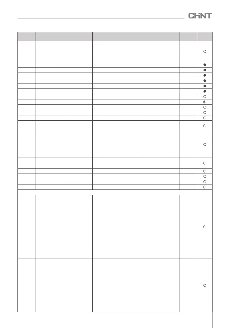
F9.16
F9.23
F9.24
F9.25
F9.26
F9.27
F9.28
F9.30
F9.31
F9.32
F9.33
F9.34
F9.29
0: When the frequency reaches the upper and lower
limits, stop integration
1: When the frequency reaches the upper and lower
limits, continue to integrate
(0.0 ~ 100.0)%
(0.00 ~ 650.00)s
0 ~ 65535
(0.0 ~ 100.0)%
(0.0 ~ 20.0)s
0: No operation when stopped
1: Calculation at shutdown
0: invalid
1: effective
0.00Hz~F0.07
0.0s ~ 6500.0s
(0.0 ~ 100.0)%
(0.0 ~ 6500.0)s
0: digital given
1:AI1
2: AI2
3: reserved
4: reserved
0
0.0%
0.00s
1000
0.0%
0.0
0
0
0.00Hz
0.0s
0.0%
0.0s
0
Integral Adjustment Options
Closed-loop preset initial value
Preset initial value hold time
Given feedback range
Feedback loss detection value
Feedback loss detection time
Closed loop operation mode
sleep function enabled
sleep frequency
sleep delay
arousal bias
wake up delay
Closed Loop Alternate Channel
Selection
F9.17
F9.18
F9.19
F9.20
F9.21
F9.22
–
–
–
–
–
–
–
–
–
–
–
–
reserve
reserve
reserve
reserve
reserve
reserve
function
code
name
Parameter Description
Defaults
Change
0x0000
0x0000
FA.00
FA.01
Simple PLC operation mode
selection
Phase 1 Setup
FA group simple PLC and multi-stage speed control group
Setting range: 0x0000 ~ 0x0112
Units: PLC operation mode
0: Stop after a single cycle
1: Keep the final value after a single loop
2: continuous loop
Tens place: Shutdown storage
0: do not store
1: Store downtime phase, frequency
Hundreds digit: power-off storage
0: do not store
1: Store power-off time stage, frequency
Thousands place: stage time unit selection
0: seconds
1 point
Setting range: 0x0000 ~ 0x0315
Units: frequency source
0: multi-band frequency N
1~5: reserved
Tens place: running direction
0: forward rotation
1: reverse
Hundreds place: Acceleration and deceleration time
0: Acceleration and deceleration time 1
1: Acceleration and deceleration time 2
2: Acceleration and deceleration time 3
3: Acceleration and deceleration time 4
099
NVF2G-S Series Inverter User's Guide
 Loading...