2-24 Installation
5150 Service Aggregation Switch Hardware Installation and Start-up Manual
009-3222-001 Standard Revision H
Copyright
©
2012-2015 Ciena
®
Corporation July 2015
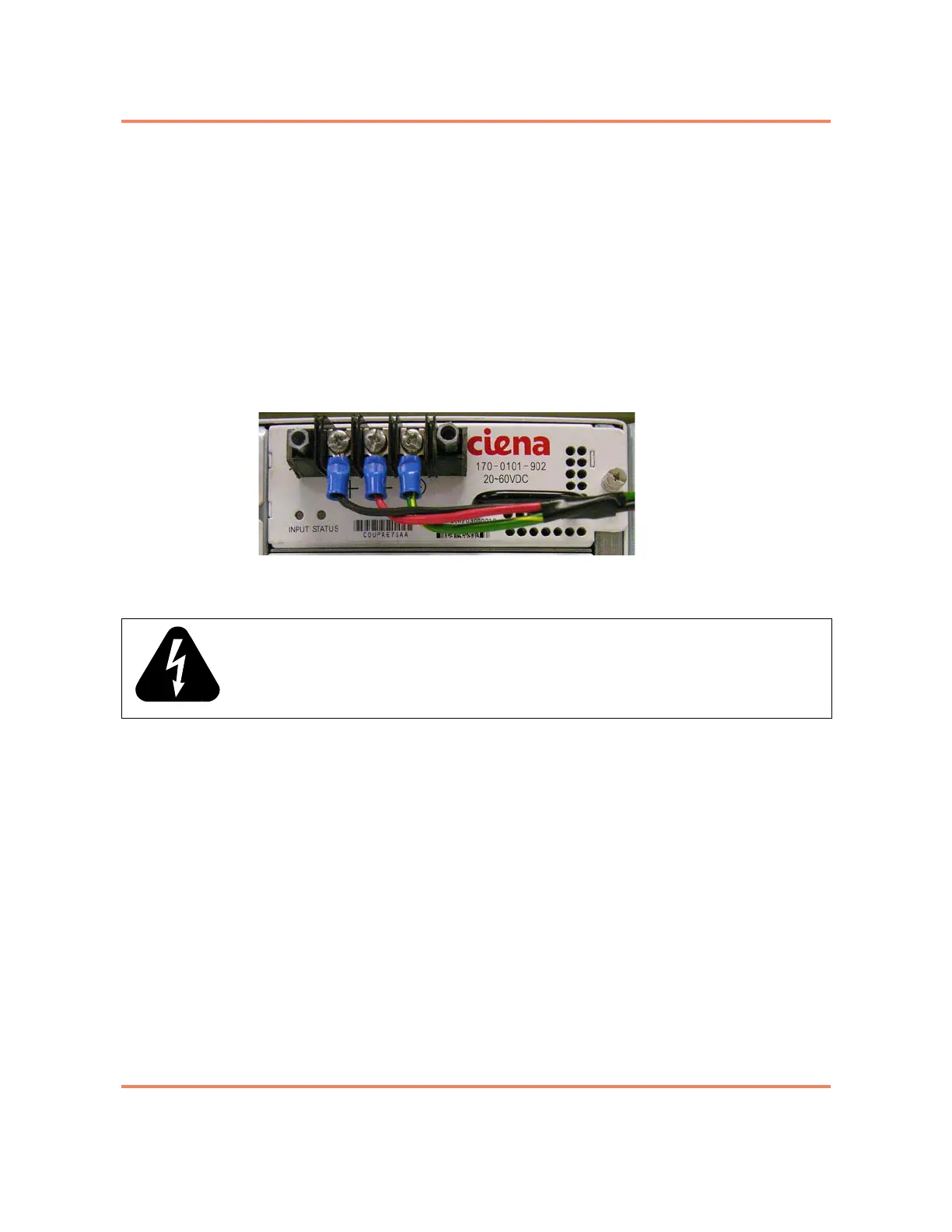
7 Use the terminal block on the front of the DC power supply to connect the
wires as follows:
• Ground — connect to the right connector
• Negative — connect to the middle connector
• Positive — connect to the left connector
Note: The ground connection should be made first. The wires should be
installed so they flow down from the terminal block. The power cabling will be
dressed to the right in
step 11.
Figure 2-8 shows the faceplate of the DC power supply with the power wiring
installed, and the plastic terminal block cover removed.
Figure 2-8
DC Power Supply (with cover removed and wiring installed)
8 Tighten the set screws on the terminal block with a Phillips screwdriver.
9 Repeat
step 7 and step 8 to connect wires to the terminal block on the front
of the second power supply.
10 Re-install the plastic terminal block covers that were removed in
step 6 on
page 2-23
.
11 Dress the power cable to the right and use a cable tie to attach the power
wires to the handle of the power supply. This helps relieve the cord weight
form the connector and avoid the inadvertent disconnection of the power
supply cord.
12 At the breaker, connect the power input wires for PS A and PS B and tighten
the set screws (if present).
Note: Separate breakers should be used for PS A and PS B. This ensures
that power can be removed from one power supply so that it can be replaced
while the unit is operating.
13 Restore power to the input DC circuit for PS A and PS B.
The power supplies will turn on.
WARNING: When making connections to the terminal block, make sure that no stray
strands of the input wire come into contact with any other part of the terminal block.