LE-3xx/LE-4xx Hardware Installation & User Guide
15
HARDWARE DESCRIPTION
1
1000BASE-X and 100BASE-FX/1000BASE-X
Each of the 1000BASE-X and 100BASE-FX/1000BASE-X uplink ports has a set of LEDs either
immediately to the right or above the port. The LE-310, LE-311, and LE-311v do not include a
PSE (pause) LED.
The following table describes the LED behavior:
The LEDs on the LE-427 are located above each port. These LEDs indicate the status of each of
the Gigabit ports.
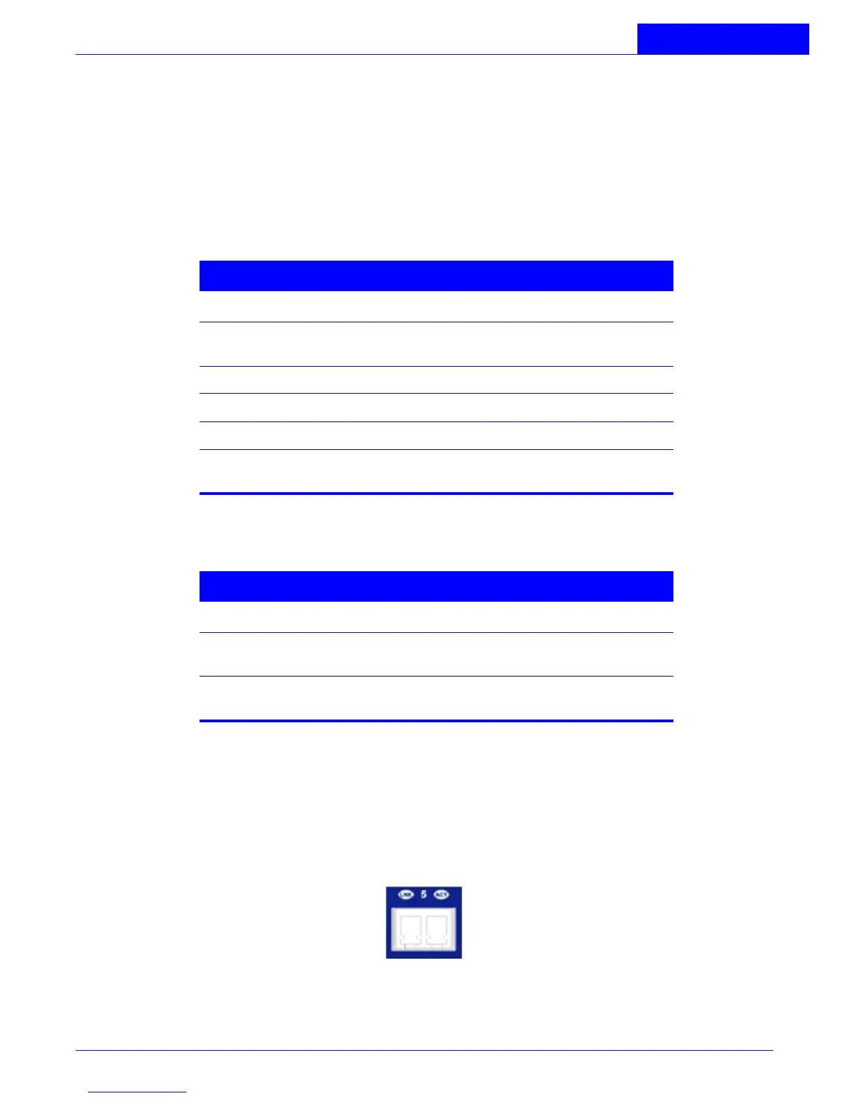
100 Mbps Subscriber Ports (LE-327)
Twenty four pairs of LEDs are associated with the 100 Mbps ports. The LE-327 has the LEDs above
the ports in the top row and below the individual ports in the bottom row. These port LEDs
indicate the status of each of the 100 Mbps subscriber ports. For convenience, each pair of LEDs
is labeled with a corresponding port number.
Figure 1-6:
100 Mbps Status LEDs (LE-327)
Table 1-5: 1000BASE-X Status LEDs
LED Indication
LK A valid network connection has been
established.
TX Port is sending data.
RX Port is receiving data.
ACT Port is active and available for use.
PSE Port is transmitting 802.3x flow control
Pause Frames.
Table 1-6: 100BASE-TX Status LEDs
LED Indication
LK Green LED indicating a valid network
connection has been established.
ACT Yellow flashing indicates port is currently
forwarding or receiving packets.