TRANSTIG 170Pi
TROUBLESHOOTING 6-14 Manual 0-5242
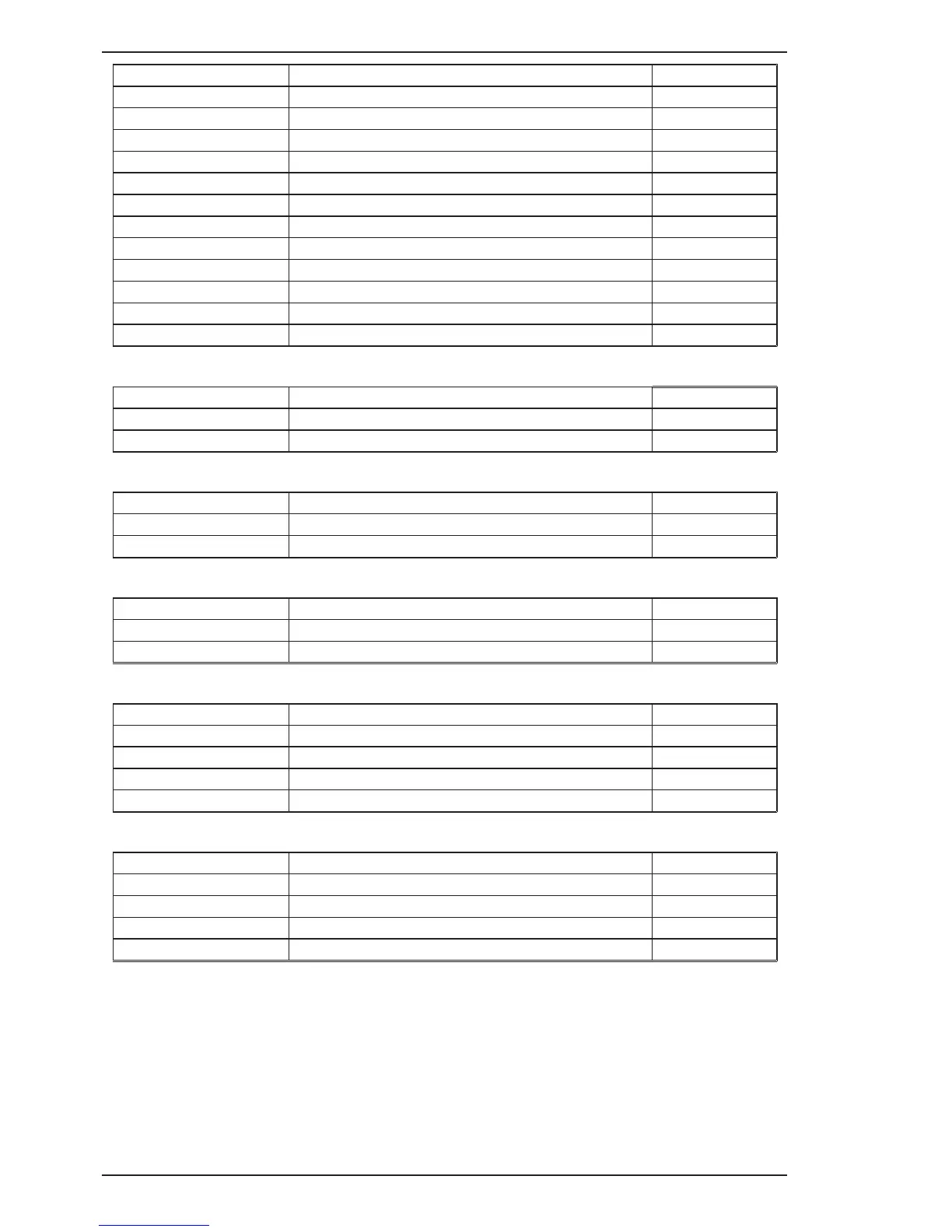
MB Header Pin Pin function Signal
1 Serial display data (LOAD) 5 VDC digital
2 Serial display data & eprom (D-IN) 5 VDC digital
3 Serial display data (CLK) 5 VDC digital
4 Serial display eprom (D-OUT) 5 VDC digital
5 DeadMan Switch (5V in DeadMan mode) 5 VDC digital
6 Encoder Output “A” (pulse output) 5 VDC digital
7 Encoder Output “D” (button) 5 VDC digital
8 Encoder direction 5 VDC digital
9 2T/4T pushbutton (0V when button pushed) 5 VDC
10 MODE pushbutton (0V when button pushed) 5 VDC
11 0V 0 VDC
12 5 VDC 5 VDC
Table 6-25: MB Header pin function (connects to J12 header on display PCB)
PFC Header Pin Pin function Signal
1 0V 0 VDC
2 PFC OK signal, 0= PFC OK
Table 6-26: PFC Header pin function (connects to JC header on inverter PCB)
OT1 Header Pin Pin function Signal
1 Thermostat
2 Thermostat
Table 6-27: OT1 Header pin function (connects to thermostat)
OT2 Header Pin Pin function Signal
1 Link to 0V
2 0V 0 VDC
Table 6-28: OT2 Header pin function (link)
HF Header Pin Pin function Signal
1 0V 0 VDC
2 HF control line (0V = HF OFF)
3 HF control line 120/240VAC (0V = 240VAC supply) 0 VDC
4 +24V 24 VDC
Table 6-29: HF Header pin function (Connects to SOUHF header on HF PCB)
IFB Header Pin Pin function Signal
1 +15V 15 VDC
2 -15V -15 VDC
3 Current sensor signal
4 0V 0 VDC
Table 6-30: IFB Header pin function (Connects to welding output current sensor)