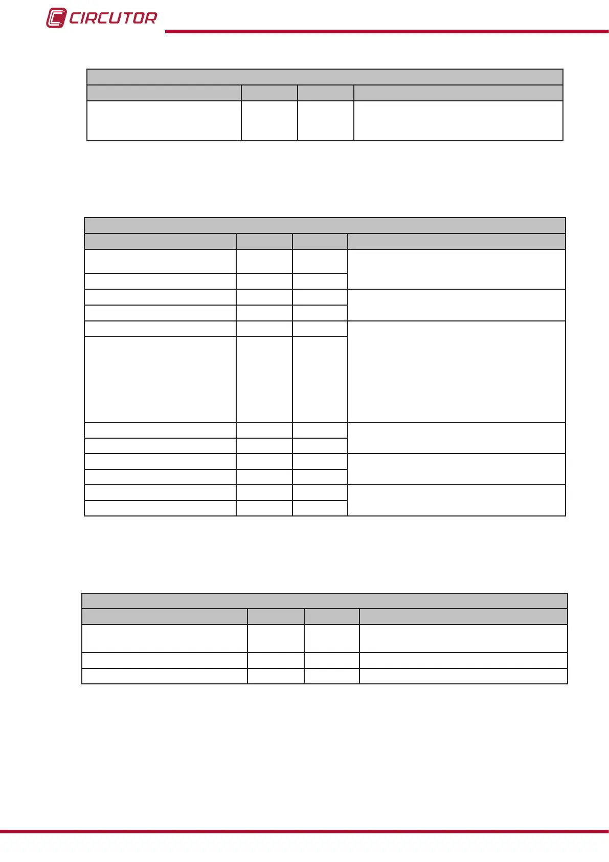
Table 14 (Continuation): Modbus memory map : Analog output
Analog output
Variable Format Address Valid data margin
Type of output int 817
0: 4 ... 20 mA
1: 0 ... 20 mA
2: 4... 12 ... 20 mA
(1)
SC: Secondary current.
6�3�5�4� Relays outputs
Table 15:Modbus memory map : Relay outputs�
Relay outputs
Variable Format Address Valid data margin
Relay 1 mode int 820
0: output is disabled.
1: alarm output
2: remote control output.
Relay 2 mode int 826
Relay 1 pulse duration int 821
0 ... 9999 ( x 0.1 s)
Relay 2 pulse duration int 827
Alarm parameter of relay 1 int 822 3: Upper current alarm
11: Upper frequency alarm
12: Alarm when Digital 1 input is connected
13: Alarm when Digital 2 input is connected
19: Lower current alarm
27: Lower frequency alarm
28: Alarm when Digital 1 input is disconnected
29: Alarm when Digital 2 input is disconnected
Alarm parameter of relay 2 int 828
Relay 1 connection delay int 823
0 ... 9999 ( x 0.1 s)
Relay 2 connection delay int 829
Relay 1 alarm value int 824
0 ... 9999
Relay 2 alarm value int 82A
Relay 1 hysteresis int 825
0 ... 9999
Relay 2 hysteresis int 82B
6.3.5.5. Conguration of the display
Table 16:Modbus memory map : Conguration of the display
Conguration of the display
Variable Format Address Valid data margin
Rotation of the display screen int 800
0: the screens don’t rotate
1 ... 60 s
Brightness of the display int 801 0 ... 4
Light alarm int 805 300 ... 1200 (x 0.1%)
36
DHC-96 Aac
Instruction Manual