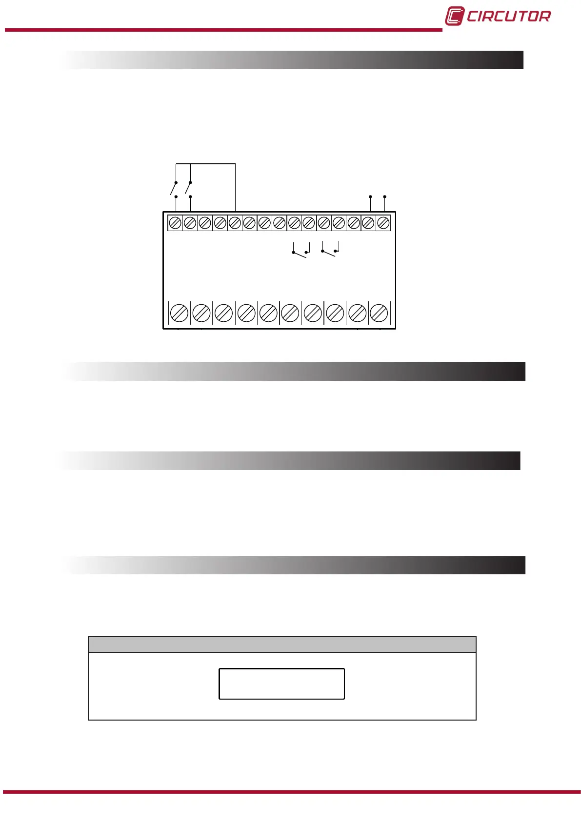
4.3.- RELAY OUTPUTS
The device features two programmable relay outputs (terminals 28, 29, 31 and 32, as shown in
Figure 6) that can be programmed as remote control signals or alarms in the setup menu (“5.4.-
RELAY OUTPUT 1” and “5.5.- RELAY OUTPUT 2”).
70 5971
1 2
72 58 28 29 31 32 1615
+-
B A
RS-485
C
1 2
1 2
45
Alimentación Auxiliar
Power Supply
Salida de relés
Digital inputs
Relay output
Analog output
Entradas Digitales
Salida Analógica
Figure 6: Relay outputs, digital inputs and Analog output�
4.4.- ANALOG OUTPUT
The device has an analog output (terminals 15 and 16 of Figure 6) programmable through the
conguration menu (“5.3.- ANALOG OUTPUT”)
4.5.- ENTRADAS DIGITALES
The device has two digital inputs (terminals 70, 71 and 72 of Figure 6). The relay outputs can be
activated depending on the value of the digital inputs (See “5.4.- RELAY OUTPUT 1” and “5.5.-
RELAY OUTPUT 2”)
4.6.- DISPLAY
The DHC-96 Aac features 4 display screens, Table 6.
Table 6: Display menu�
Display menu
Current
13
Instruction Manual
DHC-96 Aac