3-62
Cisco Aironet 1552 Series for Hazardous Locations Installation Guide
Chapter 3 Installing the 1552 Series Access Points in Hazardous Locations
Installation Details for the 1552H Access Point
Step 1 Ensure that all power sources have been disconnected from the access point.
Warning
This unit might have more than one power supply connection. All connections must be removed to
de-energize the unit.
Statement 1028
Step 2 Open the hinged cover (see the “Opening the Access Point Hinged Cover” section on page 3-58 for
instructions).
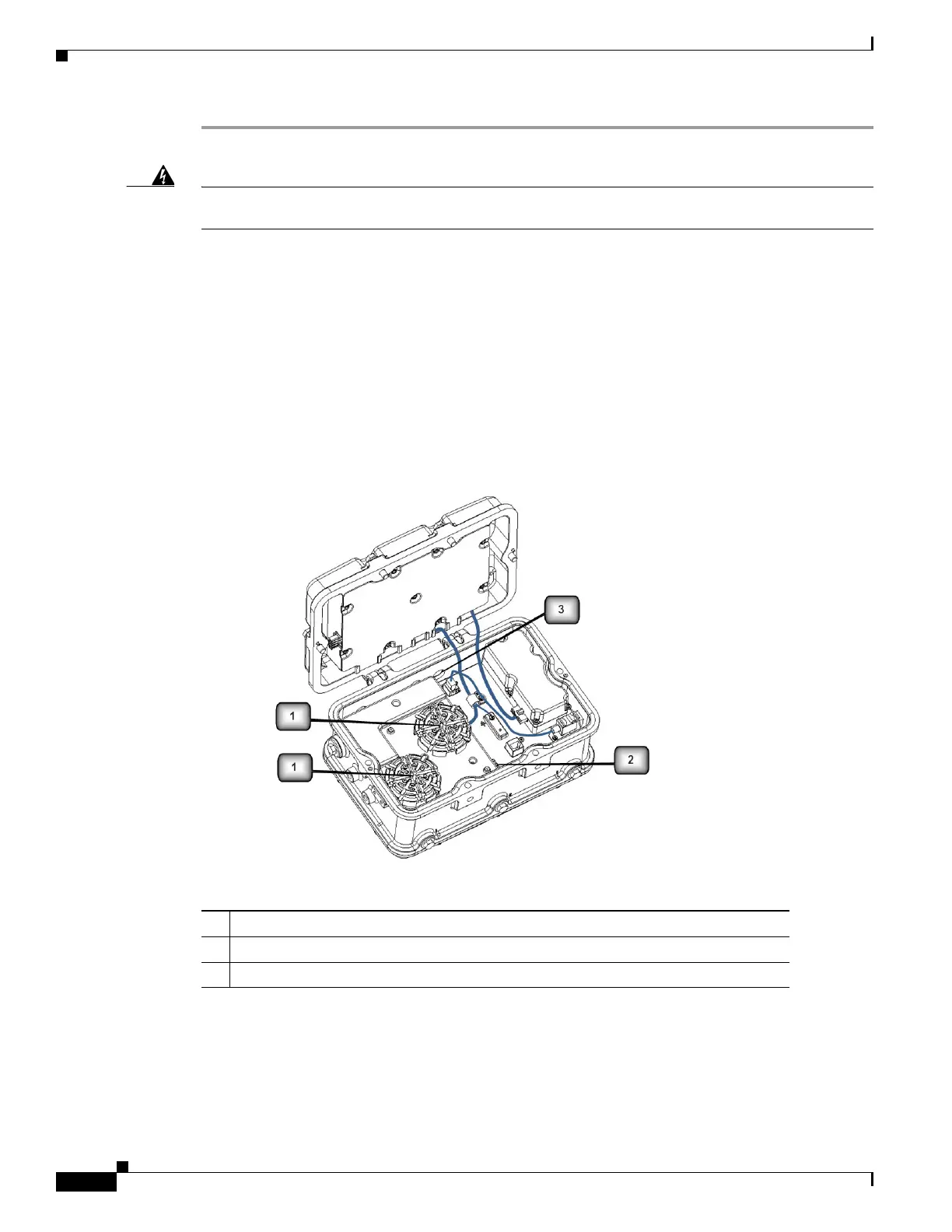
Step 3 Place the two large reels with the small reels on top as shown in Figure 3-12.
Step 4 Align the screw holes in the large and small reels, and insert four attachment screws in each of the reel
pairs. Tighten the screws to 3 to 4 in. lbs (0.34 to 0.45 Nm).
Step 5 Remove the plug from the end of the SFP module, and insert the module into the SFP receptacle (see
Figure 3-12).
Figure 3-12 Fiber-Optic Cable Components (1552H)
1 Fiber reels (large reel with small reel on top, 4 screws for each reel assembly)
2 SFP module slot
3 Fiber-optic connector port (1552H) Hole size is PG13.5