3-74
Cisco Aironet 1552 Series for Hazardous Locations Installation Guide
Chapter 3 Installing the 1552 Series Access Points in Hazardous Locations
Powering the Access Point
Note For information on data cable entry, refer to Figure 1-1 on page 1-7
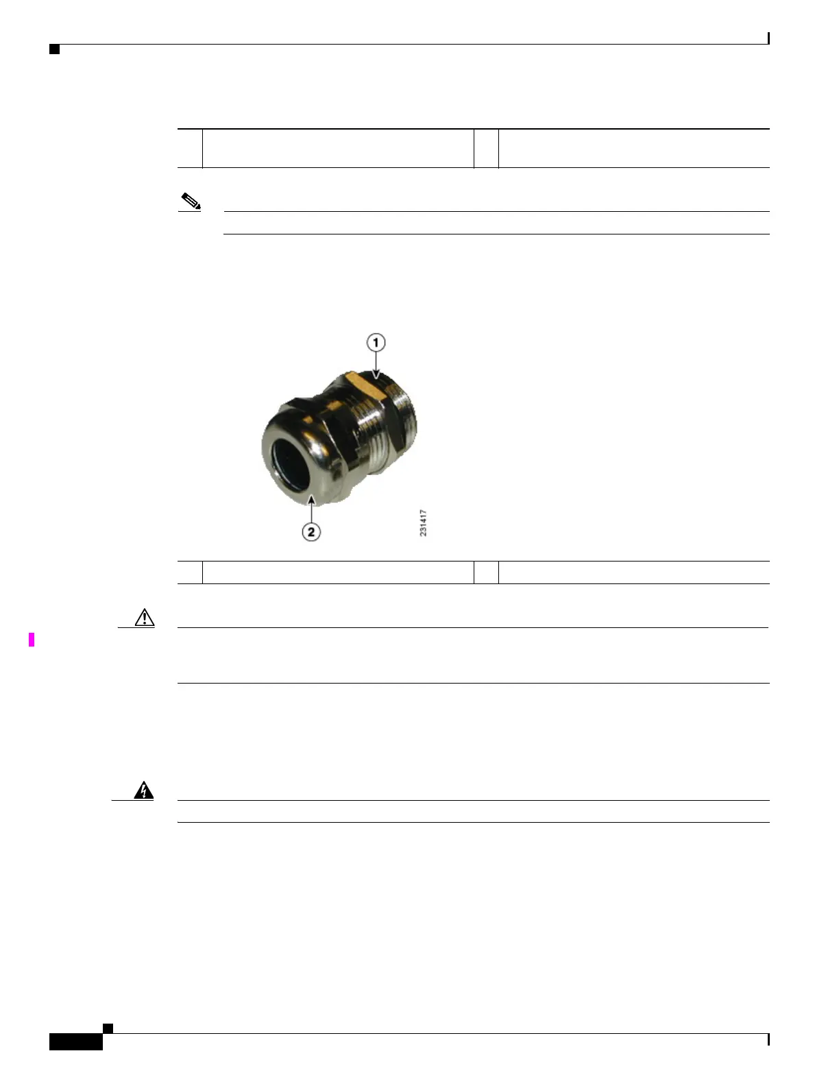
Step 4 Loosen the round end of the liquid-tight adapter by turning counterclockwise, but do not remove (see
Figure 3-21).
Figure 3-21 Liquid-tight Adapter
Caution The liquid-tight adapter(s) supplied in the kit AIR-1520-FIB-REEL= are IP68/69 certified with .200 to
.350 diameter cables but not ATEX certified or hazardous locations compliant. The installer must use
cable glands and/or adapters appropriate to the installation.
Step 5 Insert the unterminated end of the Ethernet cable into the round end of the liquid-tight adapter (see
Figure 3-21), and pull several inches of cable through the adapter.
Step 6 Install an RJ-45 connector on the unterminated end of the Ethernet cable using your Ethernet cable
installation tool.
Warning
To reduce the risk of fire, use only No. 26 AWG or larger telecommunication line cord.
Statement 1023
Step 7 Carefully insert the RJ-45 cable connector into the Ethernet port opening on the access point, and
connect to the internal Ethernet connector (see Figure 3-22).
1 ETH port (1552SA/1552SD/1552WU) or PoE
In port (1552H) Hole size PG13.5
2 PoE Out port Hole size PG13.5
1 Thread end 2 Round end