2-12 Cisco 4000 Series Hardware Installation and Maintenance
Network Connection Considerations
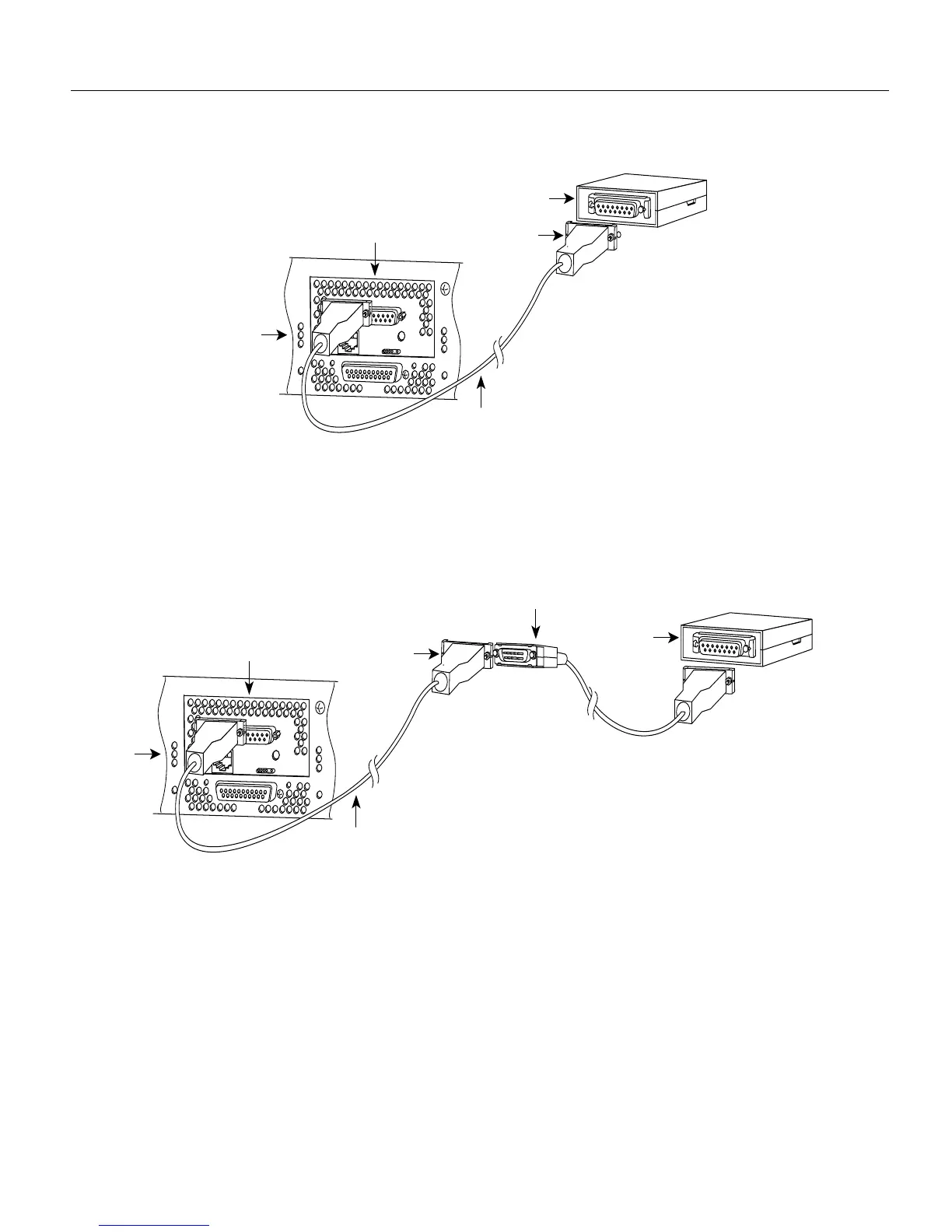
Figure 2-7 Single-Port Ethernet Network Processor Module AUI Port Connection
Figure 2-8 shows the transition cable used as a flexible extension of the Ethernet port allowing an
Ethernet transceiver cable with a slide-latch connector to mate with the female end of the 18-inch
transition cable.
Figure 2-8 Extending the Transition Cable from the Ethernet Port
Dual-Port Ethernet Module Connections
The dual-port Ethernet network processor module has ports for two network connections.
(See Figure 2-9.) The top port is marked Port-1 on the module, and the lower port is marked Port-0.
On the dual-port Ethernet network processor module, on a given port, either the Ethernet connector
or the 10BaseT connector can be used, but not both. For example, Ethernet port 0 could be attached
to either a 10BaseT connector or to an AUI connector, and similarly Ethernet port 1 could be
attached to either a 10BaseT connector or to an AUI connector.
H1525a
Transceiver
Slide-latch
connector
18" transition cable
Router
(rear view)
Ethernet module
AUI
AUX
H1526a
Slide-latch
connector
18" transition cable
Router
(rear view)
Ethernet module
AUI
Ethernet (AUI)
transceiver
Slide-latch
connector
AUX