3-12 Cisco 4000 Series Hardware Installation and Maintenance
Making Network Connections
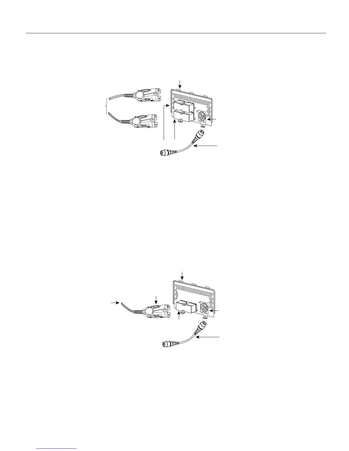
Figure 3-10 Dual-Attachment FDDI Connections
Step 2
Connect PHY-B on the FDDI module (the top port) to PHY-A on the other DAS.
Step 3 When all your network connections are complete, proceed to the section “Connecting to an
Optical Bypass Switch” later in this chapter.
Single-Attachment FDDI Connections
Step 1 Using a multimode fiber-optic cable, connect the single-attachment module’s PHY-S port
through a concentrator to a single-attachment ring, or connect it point-to-point directly to
another device. (See Figure 3-11.)
Figure 3-11 Making Single-Attachment Multimode FDDI Connections
Step 2 When all your network connections are complete, proceed to the section “Connecting to an
Optical Bypass Switch” later in this chapter.
PHY-B
PHY-B
(to PHY-A)
PHY-B
PHY-A
R
IN
G
O
P
R
IN
G
O
P
F
D
D
I
O
P
T
-B
Y
P
A
S
S
Optical
bypass switch
connector (DIN)
Dual attachment
multimode
FDDI module
Optical bypass
interface cable
PHY-A
PHY-A
(to PHY-B)
H1573a
To optical
bypass switch
MIC
connector
PHY-S
R
I
N
G
O
P
F
D
D
I
O
P
T
-B
Y
P
A
S
S
Optical
bypass switch
connector (DIN)
Single attachment
multimode
FDDI module
Optical bypass
interface cable
PHY-S
port
H1575a
To concentrator