• Terminal 3 of M12X (Green wire with white tracer) to terminal 3 of
RJ45.
• Terminal 4 of M12X (Green wire) to terminal 6 of RJ45.
• Terminal 5 of M12X (Brown wire with white tracer) to terminal 7 of
RJ45.
• Terminal 6 of M12X (Brown wire) to terminal 8 of RJ45.
• Terminal 7 of M12X (Blue wire with white tracer) to terminal 5 of
RJ45.
• Terminal 8 of M12X (Blue wire) to terminal 4 of RJ45.
5.2.2. Connecting a DC IN power source to the unit
NOTE
If the unit must be powered using an IEEE 802.3at-compliant
network switch or PoE injector, disregard this section and
proceed to “Connecting LAN cables to the unit” (page 38).
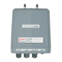
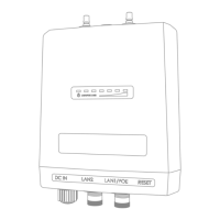
When the Cisco FM4200 Mobi is mounted in its final location, connect the
unit to a 48V DC IN power supply by doing the following steps:
1. Only use a power cable that terminates in an M12A connector to
connect the power source to the unit.
2. Make sure that the terminal pin assignments for the M12A plug
comply with the accepted standard for M12A connectors.
Next, proceed to the steps in the following table:
Cisco Ultra-Reliable Wireless
Backhaul FM4200 Mobi
© 2020 Cisco and/or its affiliates. All rights reserved. Page 37 of 177
 Loading...