EasyManuals Logo

Cisco IE 4000 Hardware Installation Guide

Cisco IE 4000
78 pages
To Next Page IconTo Next Page
To Previous Page IconTo Previous Page
Page #11 background imageLoading...
Page #11 background image
7
Product Overview
LEDs
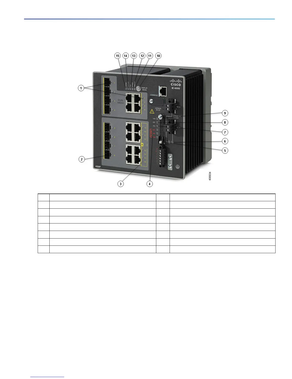
Figure 4 LEDs on the Cisco IE 4000 Switch
Display Mode Switch
The Display Mode Switch allows you to choose the mode you want displayed by the port LEDs (items 7, 8, and 9in
Figure 4 on page 7). The LEDs to the left of the switch indicate the chosen display mode. Each time you press the switch,
the mode indicator will move from Speed, Duplex, PoE, Synce, and HSR/PRP respectively.
1 Dual Media port LEDs 9 USB mini-Type B (console) port LED
2 SFP module slot LEDs 10 Display Mode Switch
3 10/100/1000 BASE-T downlink port LEDs 11 HSR/PRP
4 Alarm LEDs 12 SYNCE LED
5 Power connector DC-A LED 13 POE port status LED
6 Power connector DC-B LED 14 Duplex LED
7 System LED 15 Speed
8 Express Setup LED

Other manuals for Cisco IE 4000

Questions and Answers:

Question and Answer IconNeed help?

Do you have a question about the Cisco IE 4000 and is the answer not in the manual?

Cisco IE 4000 Specifications

General IconGeneral
Product TypeSwitch
Form FactorDIN Rail Mountable
MAC Address Table Size8000
Jumbo Frame Support9216 bytes
Operating Temperature-40°C to 70°C
Mean Time Between Failures (MTBF)Over 500, 000 hours
Memory256 MB DRAM
MountingDIN Rail, Wall
CertificationsEN 50121-4
Ports8 x 10/100Base-TX Ethernet Ports

Related product manuals