31
Switch Installation
Connecting Alarm Circuits
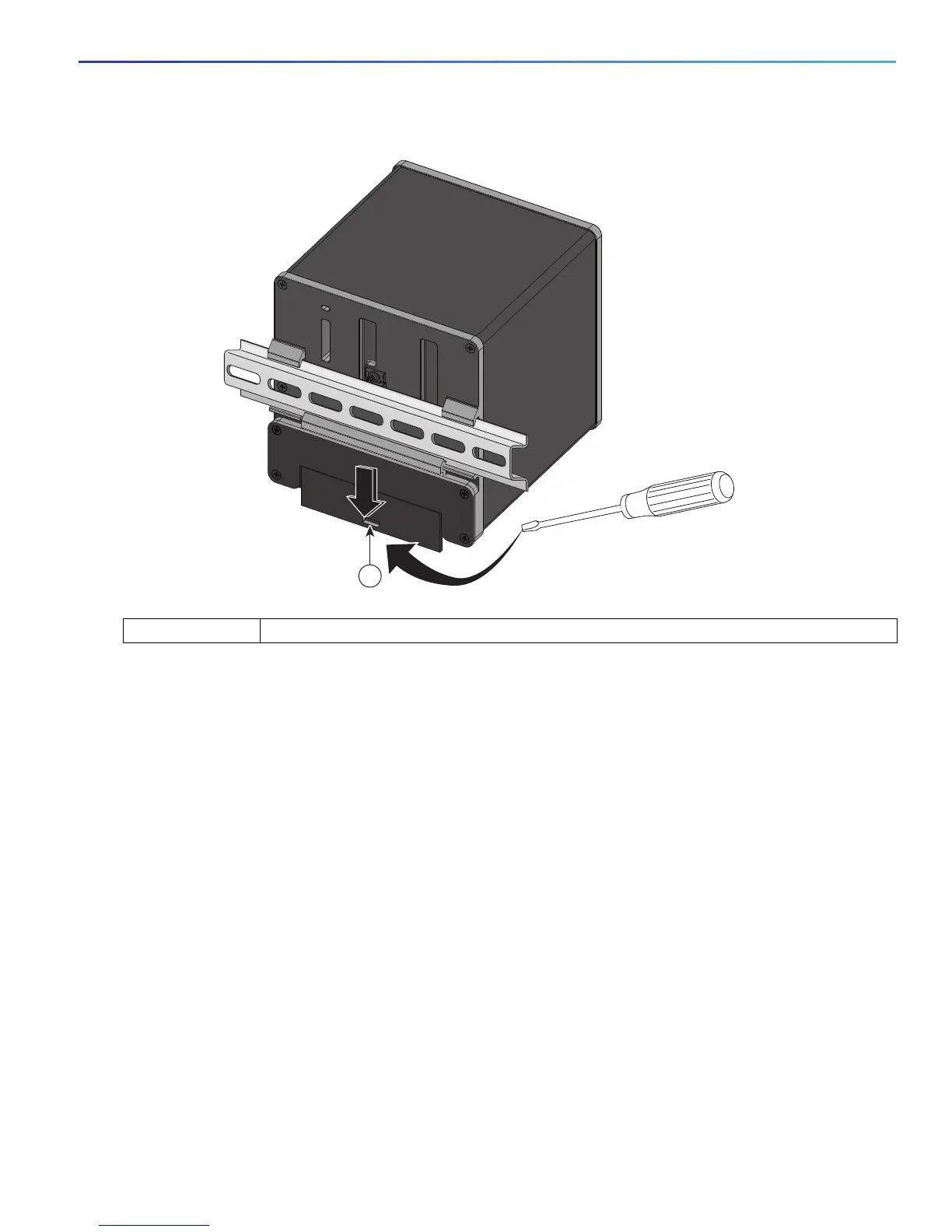
Figure 15 Releasing the Spring-Loaded Latch from the DIN Rail
4. Remove the switch from the DIN rail.
Connecting Alarm Circuits
After the switch is installed, you are ready to connect the DC power and alarm connections.
Wiring the Protective Ground and DC Power for Alarm Circuits, page 31
Wiring the External Alarms, page 31
Wiring the Protective Ground and DC Power for Alarm Circuits
For instructions on grounding the switch and connecting the DC power, see the Grounding the Switch, page 19.
Wiring the External Alarms
The switch has two alarm input and one alarm output relay circuits for external alarms. The alarm input circuits are
designed to sense if the alarm input is open or closed relative to the alarm input reference pin. Each alarm input can be
configured as an open or closed contact. The alarm output relay circuit has a normally open and a normally closed
contact.
1 Push latch down
331953
1

 Loading...


