9
Product Overview
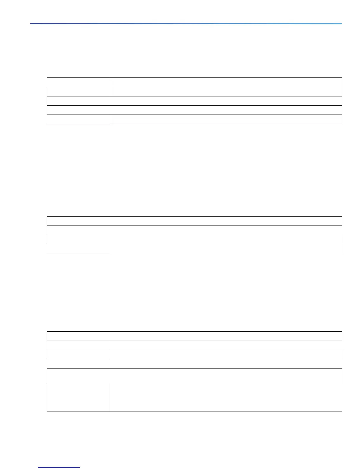
LEDs
Alarm IN1 and IN2
Power Status LEDs
The switch can operate with one or two DC power sources. Each DC input has an associated LED that shows the status
of the corresponding DC input. If power is present on the circuit, the LED is green. If power is not present, the LED color
depends on the alarm configuration. If alarms are configured, the LED is red when power is not present; otherwise, the
LED is off.
If the switch has dual power sources, the switch draws power from the power source with the higher voltage. If one of
the DC sources fails, the alternate DC source powers the switch, and the corresponding power status LED is green. The
power status for the failed DC source is either off or red, depending on the alarm configuration.
The Power A and Power B LEDs show that power is not present on the switch if the power input drops below the low
valid level. The power status LEDs only show that power is present if the voltage at the switch input exceeds the valid
level.
For information about the power LED colors during the boot fast sequence, see Verifying Switch Operation, page 39.
Port Status LEDs
Each port and SFP uplink slot has a status LED, as shown in Figure 4 on page 7 and described below.
Color System Status
Off Alarm IN1 or IN2 not configured.
Green Alarm IN1 or IN2 configured, no alarm detected.
Blinking red Major alarm detected.
Red Minor alarm detected.
Color System Status
Green Power is present on the associated circuit, system is operating normally.
Off Power is not present on the circuit, or the system is not powered up.
Red Power is not present on the associated circuit, and the power supply alarm is configured.
Color System Status
Off No link.
Solid green Link present.
Blinking green Activity. Port is sending or receiving data.
Alternating
green-amber
Link fault. Error frames can affect connectivity, and errors such as excessive collisions, CRC
errors, and alignment and jabber errors are monitored for a link-fault indication.
Solid amber Port is not forwarding. The port was disabled by management, an address violation, or STP.
After a port is reconfigured, the port LED can remain amber for up to 30 seconds while STP
checks the switch for possible loops.

 Loading...


