24
Switch Installation
Connecting to Power
Figure 9 Stripping the Power Connection Wire
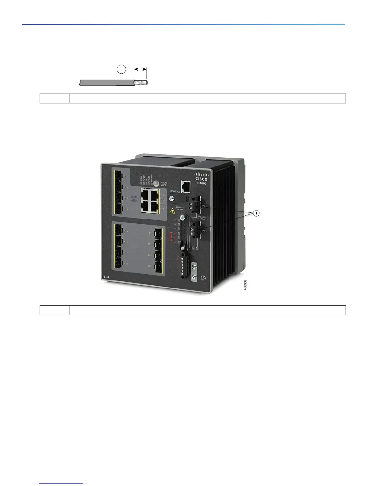
5. Remove the two captive screws that attach the power connector to the switch, and remove the power connector.
Remove both connectors if you are connecting to two power sources. See Figure 10 on page 24.
Figure 10 Removing the Power Connectors from the Switch
6. On the power connector, insert the exposed part of the positive wire into the connection labeled “+” and the exposed
part of the return wire into the connection labeled “–”. See Figure 11 on page 25. Make sure that you cannot see any
wire lead. Only wire with insulation should extend from the connector.
Warning: An exposed wire lead from a DC-input power source can conduct harmful levels of electricity. Be sure that
no exposed portion of the DC-input power source wire extends from the connector(s) or terminal block(s).
Statement 122
1 0.25 in. (6.3 mm) ± 0.02 in. (0.5 mm)
1 Power Connectors

 Loading...


