3-6
Catalyst 4500 E-Series Switches Installation Guide
OL-13972-02
Chapter 3 Installing the Switch
Installing the Switch in a Rack
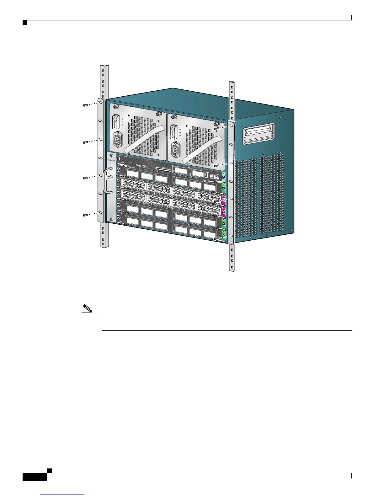
Figure 3-1 Installing the Switch in the Rack (Catalyst 4506-E Switch Shown)
a. Attach the cable guide, if needed, using the M3 screws provided in the cable management kit. The
cable guide attaches to prethreaded holes in either L
bracket. (See Figure 3-2.)
Note We recommend that you attach the cable guide to the right side of the switch chassis to prevent
the network interface cables from obscuring switching module front panel LEDs.
231371
4506
 Loading...


