4-7
Catalyst 4500 E-Series Switches Installation Guide
OL-13972-02
Chapter 4 Removal and Replacement Procedures
Removing and Installing the AC-Input Power Supplies
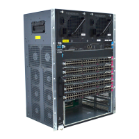
Figure 4-7 Plugging the Power Cord into the Power Supply
Step 9 Plug the other end of the power cord to source AC.
Note In a chassis with dual power supplies or power supplies with multiple AC inputs, connect each
AC power cord to a separate source AC circuit.
Step 10 Set the power switch to the on (|) position (see Figure 4-8).
Figure 4-8 Powering On the Power Supply
Step 11 Verify the power supply operation by checking the power supply’s front-panel LEDs. You should see the
following:
• The LED labeled GOOD is green.
• The LED labeled FAIL is not lit.
• The LED labeled FAN OK is green.
Step 12 Check the power supply and system status from the system console by entering show power command.
For more information on this command, see the command reference publication for your switch.
Step 13 If the LEDs or show power command output indicate a power problem or other system problem, see
Chapter 5, “Troubleshooting,” for more information.
79142
Power switch
79143
 Loading...


