4-17
Catalyst 4500 E-Series Switches Installation Guide
OL-13972-02
Chapter 4 Removal and Replacement Procedures
Removing and Installing the Backplane Modules
Step 7 If you are removing a clock module, remove the two screws that secure the clock module to the
backplane.
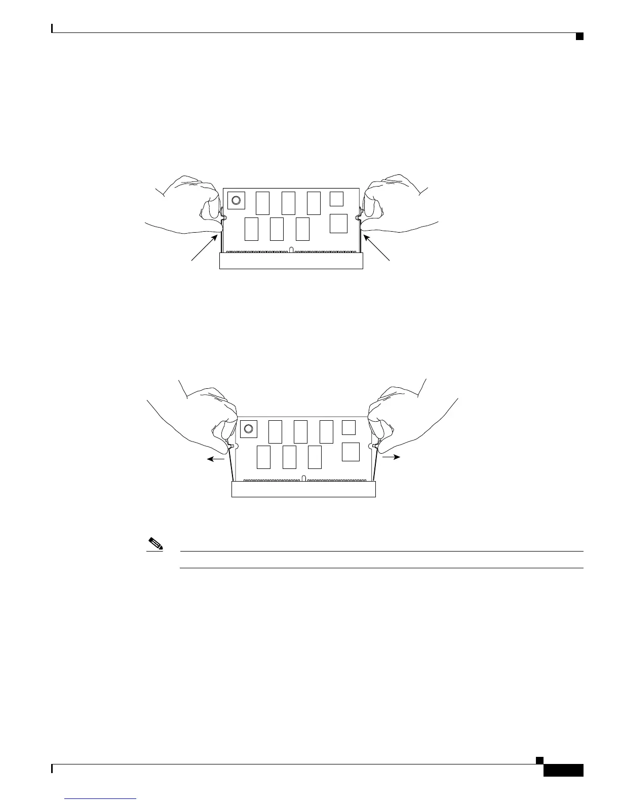
Step 8 Locate the seating levers on both sides of the connector for the module that you want to replace. (See
Figure 4-17.)
Figure 4-17 Finding the Seating Levers
Step 9 To release the module from its connector, pull the levers outward with your fingernails. The module will
pop out slightly. (See
Figure 4-18.)
Figure 4-18 Releasing the Module
Step 10 Pull the module out of the connector by grasping the top left and right corners. (See Figure 4-19.) Place
the old module in an antistatic bag or on an antistatic foam pad.
Note When handling the modules, do not touch the chips or the gold edge contacts on the module.
130658
130659
 Loading...


