• You must carry electronic modules by only their covered edges or handles. Do not touch their
electronic components.
• Whenever a module is outside a grounded chassis, place it flat on an antistatic surface or in an
antistatic bag. Never lean the module on anything nor place anything else on top of the module nor
lean anything on the module.
• Verify that the chassis is grounded.
• Verify that you have the following tools and equipment:
• ESD wrist strap (or other personal grounding device)
• Number 1 Phillips torque screwdriver
• Manual torque screwdrivers are recommended. Be sure to never exceed the recommended torque
setting for the screw that you are working with.
• Ensure that sufficient quantity of Cisco MDS Crossbar Fabric-3 Switching Modules (6 modules are
supported in a Cisco MDS 9000 Series Multilayer Director) are available for replacing the current Cisco
MDS Crossbar Fabric Switching Modules in the switch.
It is not supported to mix different crossbar fabric switching modules (Crossbar Fabric-1 Switching Module
and Crossbar Fabric-3 Switching Module) outside a maintenance window. This mix of modules is supported
only while you are migrating from Fabric-1 modules to Fabric-3 modules. After a reboot of the switch, if
there is a mix of Fabric-1 and Fabric-3 modules, only the Fabric-3 modules will be powered on.
Warning
Ensure that there is no loose debris (such as paper, ties, dust) around the back of the chassis when the crossbar
switching modules are being removed. When the crossbar switching modules are pulled, the vacuum created
can be strong enough to pull the loose debris into the chassis.
Warning
Step 1 Shut down the crossbar fabric switching module to be replaced by using the out-of-service xbar slot command (where,
slot refers to the external crossbar fabric switching module slot number).
Step 2 Remove the fan module that is over the crossbar fabric switching module to be removed. For more information on how
to remove a fan module, see Installing and Removing Fan Modules, on page 175. Crossbar fabric switching modules are
numbered 1-6, from left to right, when facing the rear of the chassis. If the system is running, remove only one fan module
at a time to access the required crossbar fabric switching module.
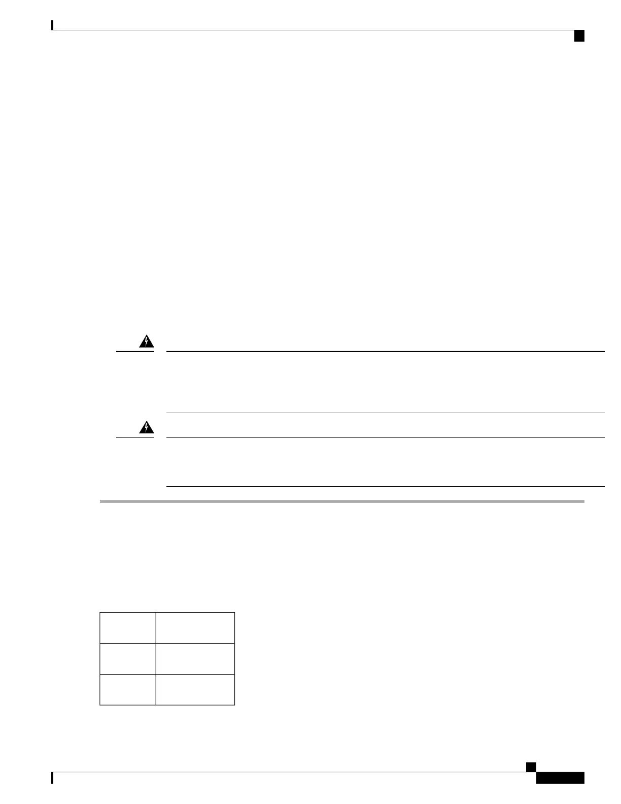
The positioning of the fan modules and respective crossbar fabric switching modules is as follows:
Fabric modules
1-2
Fan module
1
Fabric modules
3-4
Fan module
2
Fabric modules
5-6
Fan module
3
Cisco MDS 9700 Series Switches Hardware Installation Guide
157
Installing, Removing, and Verifying Field Replaceable Units
Installing a Crossbar Fabric Switching Module
 Loading...


