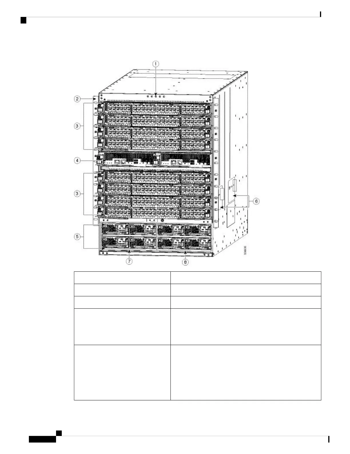
Figure 3: Cisco MDS 9710 Chassis Front View
Chassis LEDs1
Chassis mounting brackets2
I/O modules slots numbered 1-4 and 7-10 from top to bottom3
Supervisor modules (one or two) in slots numbered 5 and 6 from
left to right.
Each slot is half the width of the chassis and each slot can hold
one supervisor module
4
Power supplies (up to 8 bays).
• There are two rows of power supply bays at the bottom of
the chassis. Each bay can hold one power supply.
• The top row has bays 1-4, numbered left to right.
• The second row has bays 5-8, numbered left to the right.
5
Cisco MDS 9700 Series Switches Hardware Installation Guide
16
Product Overview
Cisco MDS 9710 Director Chassis
 Loading...


