Grid A PSU bays (1, 2 slots)8
Grid B PSU bays (3, 4 slots)9
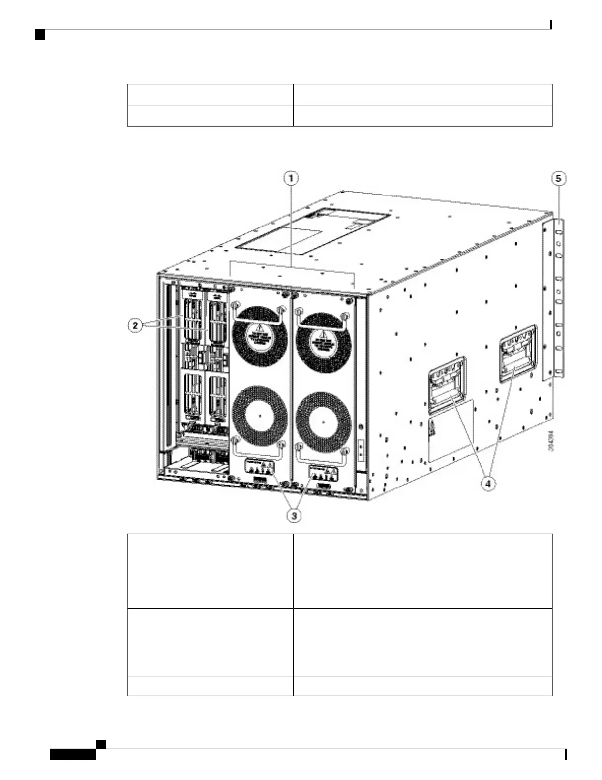
The following figure shows the rear view of the Cisco MDS 9706 chassis.
Figure 6: Cisco MDS 9706 Chassis Rear View
Fan modules - (Three fan modules) 1-3 are numbered left to the
right. When the fan modules are installed, they cover the crossbar
fabric switching modules.
Only two fan modules are shown in the figure. One fan module
is removed to show the crossbar fabric switching module in back.
1
Crossbar fabric switching modules - (up to six crossbar fabric
switching modules with two modules behind each fan module).
The crossbar fabric switching modules 1 and 2 are behind the fan
module 1, fabric modules 3 and 4 are behind the fan module 2,
and fabric modules 5 and 6 are behind the fan module 3.
2
Crossbar fabric switching modules and fan LEDs3
Cisco MDS 9700 Series Switches Hardware Installation Guide
20
Product Overview
Cisco MDS 9706 Director Chassis
 Loading...


