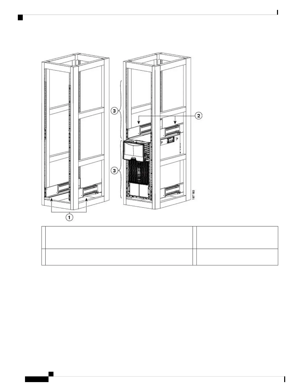
Figure 33: Positioning the Bottom-Support Rails
Allow at least 36.75 inches (93.4 cm)
(21 RU) for each Cisco Nexus 7010
system.
3For the first and heaviest Cisco Nexus 7010 chassis installed in a rack,
position two bottom-support rails at the lowest RU on the rack.
1
For the second Cisco Nexus 7010 chassis installed in a rack, position two
bottom-support rails immediately above the first installed switch.
2
Step 2 Use a Phillips screwdriver to screw in three M6 x 19 mm or 12-24 x 3/4 in. Phillips screws on each end of each rail (using
a total of 12 screws for both brackets) as shown in Figure 34: Attaching a Bottom-Support Rail to a Rack, on page 75.
Three of the screw holes on each end of the bottom-support rail align to the screw holes in the mounting rail.
Use a screw in each of these screw holes.
Note
Cisco Nexus 7000 Series Hardware Installation and Reference Guide
74
Installing a Cisco Nexus 7010 Chassis
Attaching the Bottom-Support Rails
 Loading...


