Service Manual-CA60 34 Scrub System REV (CA60 20B/24B) 60
34 Scrub System, REV(CA60 20B/24B)
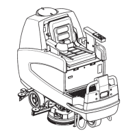
Functional Description
The REV brush system can be operated by the operator.
The REV brush has a movement with distinctive orbital movements and anticlockwise rotation.
The REV allows the surface concerned to be washed/ cleaned by the movement of the brush. The main component of the
system is the deck where the brush or the pad suitable for the type of surface to be cleaned is installed.
The brush deck is fixed to the machine with a support to which the electrical actuator and two anchor levers are applied.
The electrical actuator (M5) lifts and lowers the deck. The operating and washing pressure depends on the weight of the
deck. The actuator also permits the extra pressure function. Extra pressure is selected via the button on the dashboard.
Brush rotation occurs only when the REV motor (M1) is driven by one of the handle switches.
Transmission of motion from the gear motor to the brush occurs via an eccentric system which provides the orbital
movement.
The system, once activated, uses the solution coming from the solution system, to wash the floor.
In case of REV motor overload, The Circuit Breaker F1 will stop the brush to prevent continuous overload.
To start scrubbing again after a brush stop due to overload, turn the machine off, reset the circuit breaker F1, turn the
machine on.
In summary, operation of the REV motor (M1) requires the following conditions/inputs:
Brush function on
One of the two handle switches is pressed
Battery level not in critical condition with flashing segment
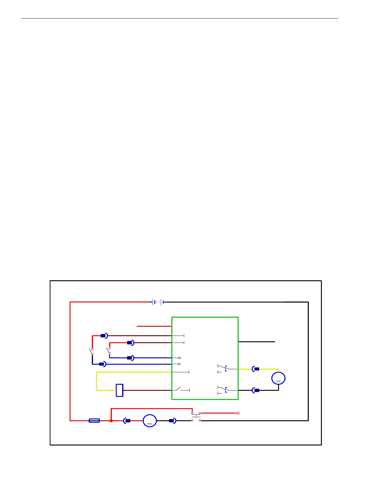
Wiring Diagram