Service Manual-CA60 24-Electrical System 33
24 Electrical System
Functional Description
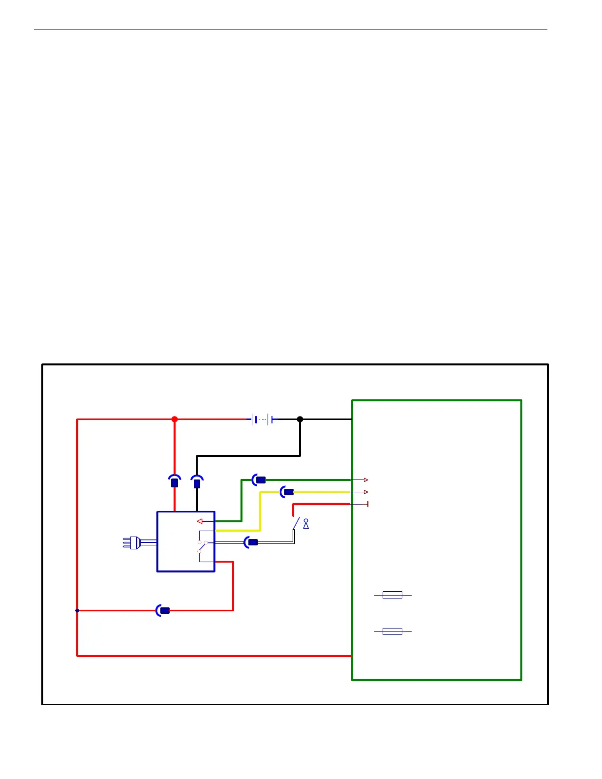
The batteries (2 x 12V) are connected together in series by the cables.
The battery charger (CH1) is connected to the machine by two connectors (C1) (power connection to the batteries) and J1 (4-
way signal connection).
The red/black and white cables (3 and 4 of connector J1) are normally connected inside the battery charger CH1 when the
battery charger is not connected to the mains. When the battery charger is plugged into the mains, the connection between 3
and 4 of connector J1 is broken and which causes all machine functions to be disabled. At the same time a connection is
made between 3 and 5 of j1 which provides power for the E1main control board during the charging cycle so that the control
panel can display the current charging status to the operator.
The battery charger and main control board communicate through a dedicated wire. This communication connection allows
the battery charger charging curve to be set directly from the machine dashboard and to view the operational state of the
battery charger during charging directly on the dashboard display. When the charger is plugged into the mains, it checks with
the main controller to find out what type of batteries are installed in the machine so that it can use the correct charging curve.
Battery Charger Wiring Diagram