Service Manual-CA60 40 Recovery System 82
40 Recovery System
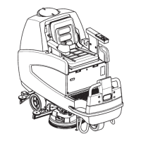
Functional Description
The recovery system removes dirty water from the floor and pipes it to a recovery tank. When the machine is
running, the dirty water on the floor is collected by the squeegee blades and collected through the slots in the same,
piped through the vacuum hose and into the tank by airflow created by vacuum motor (M2). The dirty water is piped
into the recovery tank, while the airflow continues to the vacuum fan.
A tank with a grid collects the largest debris going through the recovery tank hose.
The automatic float in the vacuum grid stops vacuum system motor (M2) from collecting any liquids.
The vacuum system is activated automatically with the One-Touch button. It can then be managed independently
via the vacuum button.
When the recovery tank is full it can be emptied through the drain hose.
To work properly, the vacuum motor (M2) needs the following:
Vacuum function on
Battery level not in critical condition with flashing segments.
When turn off the vacuum motor, the vacuum LED on dashboard will flash 5 seconds, then disable the vacuum
motor.
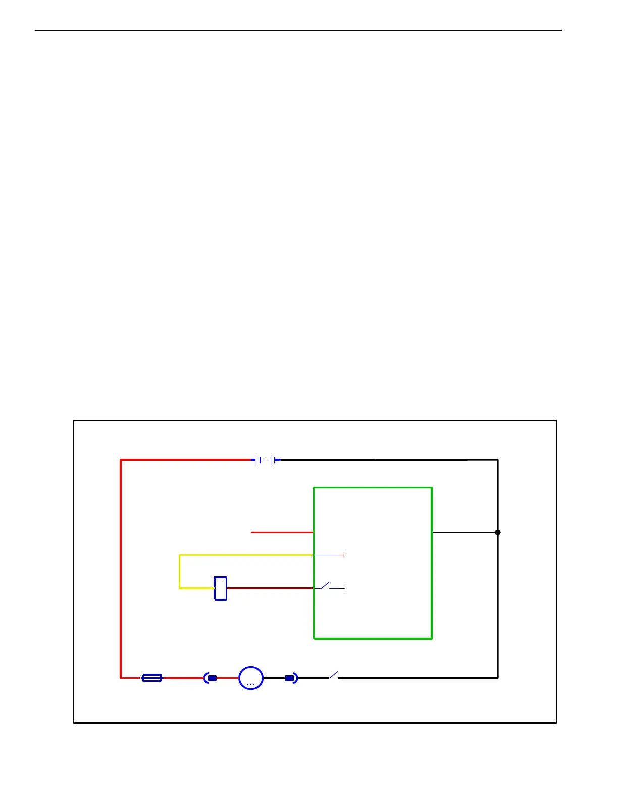
Wiring Diagram