MAN.161 Rev.7 ENG - Use and maintenance manual S15 page
14
of
71
• SS travel speed selector (Picture 5): moving the selector to the
left, it selects the travel speed in “turtle” mode, while to the right the
higher one in “hare” mode.
On the frame of the MEWP, there are stickers with coloured arrows
that indicate the directions of travel set on wired remote control.
If the triple speed is present as an optional, to activate it, push the
joysticks J1 and J2 to the maximum in concordance (both upwards or
both downwards).
• travel consent light 3 (Picture 5): orange light, which, if it is ON,
indicates the consent to travel operations.
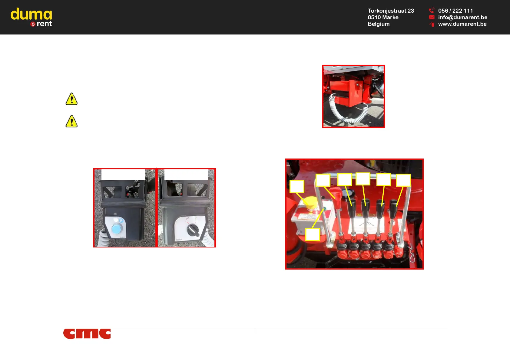
Picture 6: left and right side of wired remote control.
On the left side of the wired remote control, there is:
• P parking button (Picture 6): located on the left side of the wired
remote control, if kept pressed, it allows the vertical movement of
the tracks with the machine stabilized, in case of their replacement.
On the right side of it, there is:
• selector for parking operations or travel operations (Picture 6).
The remote control is placed in the special aluminium case showed in Pic-
ture 7. To work, it must be correctly connected to its connector.
Picture 7: location for remote wired control.
3.2.2
Outriggers control station
Picture 8: outriggers control station.
The outriggers control station (Picture 8) is positioned on the left side of the
frame and, through it, it is possible to perform manual stabilization / desta-
bilization of the MEWP. It consists of: