MAN.161 Rev.7 ENG - Use and maintenance manual S15 page
15
of
71
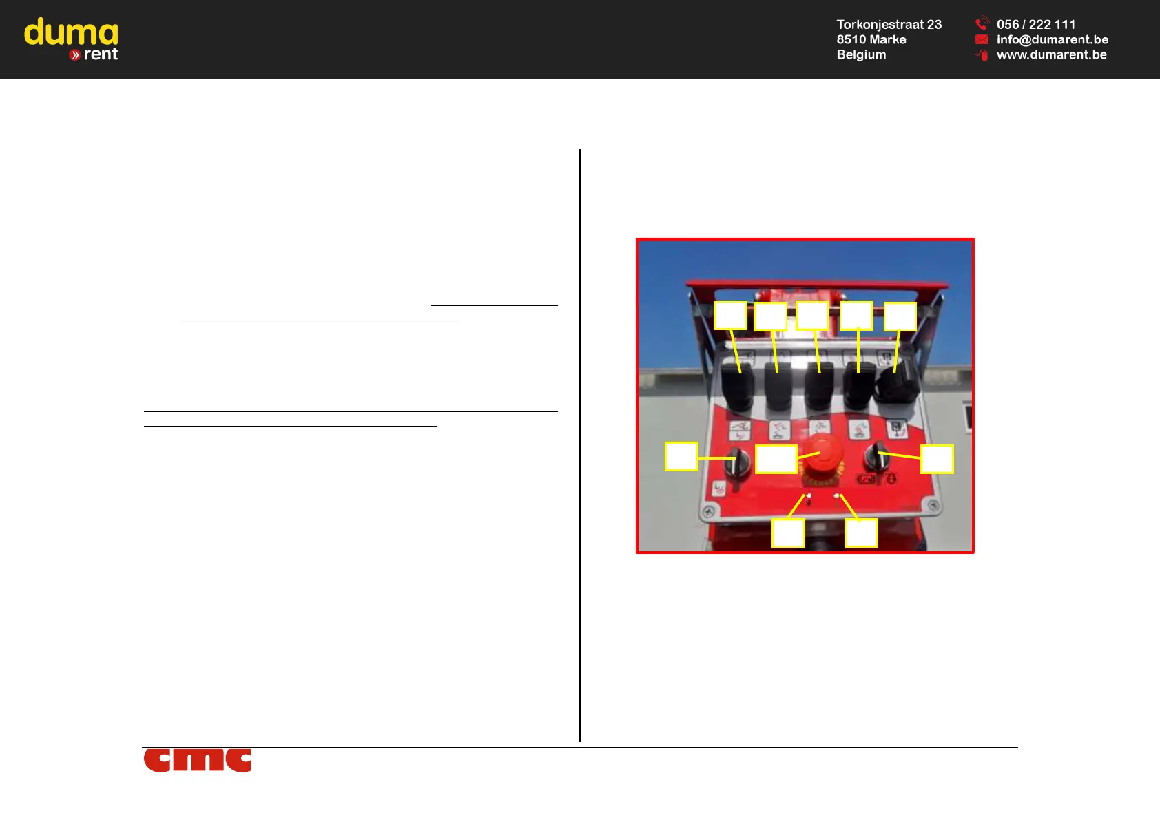
- front left outrigger lever 1 (Picture 8);
- front right outrigger lever 2 (Picture 8);
- rear right outrigger lever 3 (Picture 8);
- rear left outrigger lever 4 (Picture 8);
- tracks extraction/retraction (*optional) red lever 5 (Picture 8);
- “dead man” stabilizers button 6 (Picture 8): it must be held pressed
together with other levers to stabilize or destabilize.
- electrical power supply warning light 7 (Picture 8): green light,
which, if it is ON, indicates that the MEWP is correctly and electrically
powered.
For each lever, pushing it down, the lowering of the outriggers is produced;
pushing it upwards, execute the re-entry of the same.
3.2.3
Platform operating control station
The platform (operating) control station is positioned inside the basket. If the
machine is equipped with petrol/diesel engine or in hybrid version, it consists
of (Picture 9a):
Picture 9a: platform (operating) control station
for endothermic equipment.
• movement lever group (listed from left to right):
- joystick 1 for jib extension/retraction / basket levelling (Picture
9a): downwards it makes the jib retraction or the internal levelling;
upwards the jib extension or the external levelling.
- joystick 2 for extension/retraction of boom (Picture 9a): down-
wards it produces the boom return, upwards the extension.