MAN.161 Rev.7 ENG - Use and maintenance manual S15 page
11
of
71
2.3.1
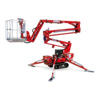
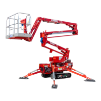
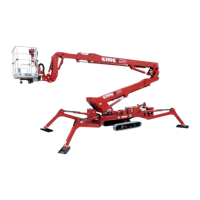
Frame
The frame 1
(Picture 3)
,
in quality steel structure, equally divide the equip-
ment’s weight when the MEWP is in transport position. The frame has 4 oil-
pressure jack booms for stabilization [2 front stabilizer cylinders 2 (Picture
3), 2 rear stabilizer cylinders 3 (Picture 3)]. The basis for the bearing is
placed on the frame 4 (Picture 3), it enables the swinging of the equipment
through the rotation group.
2.3.2
Turret
The turret 5 (Picture 3), in quality steel, is fixed on the bearing. It is started
by a hydraulic engine (whose brake is normally closed), placed inside the
turret. It enables the rotation of the superstructure.
2.3.3
Pantograph
The pantograph 6 (Picture 3) is composed by two couples of parallel booms
and by the pantograph connecting rod 7 (Picture 3). The booms (tubular with
rectangular section, press-formed and electro welded) and the connecting
rod are in quality steel sheets. The movement of the pantograph (panto-
graph lifting and descent) is realized by the pantograph lifting oil-pressure
cylinder. This cylinder is hinged to the turret (rod side) and to the pantograph
upper crank (stem side) and it has a double effect balancing valve This cyl-
inder is hinged to the turret.
2.3.4
Telescopic boom
The telescopic boom 8 (Picture 3) is hinged to the turret. The telescopic
boom is composed by two elements: 1 fixed boom, hinged to the pantograph
connecting rod, and 1 sliding boom.
The sliding or re-entry movement of the telescopic boom is activated by op-
erating the “telescopic boom sliding cylinder device”.
The lifting or descent movement of the telescopic boom is activated by op-
erating the “telescopic boom lifting cylinder device”.
2.3.5
Jib
At the end of the telescopic boom is hinged an boom named Jib 9 (Picture
3). The lifting or descent of the jib is done by operating the “Jib lifting cylin-
der” 10 (Picture 3).
2.3.6
Basket
In aluminium tubular, the basket 11 (Picture 3) has a lateral opening to allow
the entrance of the operators. The lateral opening is an auto-shutter and
built to avoid accidental openings. The basket has strong points for safety
belts, a guard-rail 1,1 m high from the basket floor, an intermediate guard-
rail and a foot protecting band along all sides of the platform. The floor is in
antiskid and auto-draining aluminium. The basket is removable: it is con-
nected to a support through which it is possible to couple it with the jib.