MAN.161 Rev.7 ENG - Use and maintenance manual S15 page
13
of
71
When the state of batteries charge, during the use, reaches the
lowest level (under 10%), all work maneuvers will be interrupted,
and it will only be possible to close the machine again.
It is absolutely forbidden to direct high-pressure jets of water
onto the support containing the battery pack.
High water pressure could generate serious and irreversible
problems in the operation of the machine.
3.2
Platform control stations
The command stations of the platform are:
• the travel control station (Picture 5);
• the outriggers controls (Picture 8);
• the operating control station, placed on the basket, for the use of the
aerial part (Picture 9),
• the emergency one, placed on the turret, for the recovery of the aerial
part from the ground (Picture 11).
It is not possible to use two different command stations at the
same time.
3.2.1
Travel control station
Check that there is nobody in the travel area and that the ma-
chine is in transport configuration (jib closed, pantograph and
boom on support, centered turret, stabilizers raised).
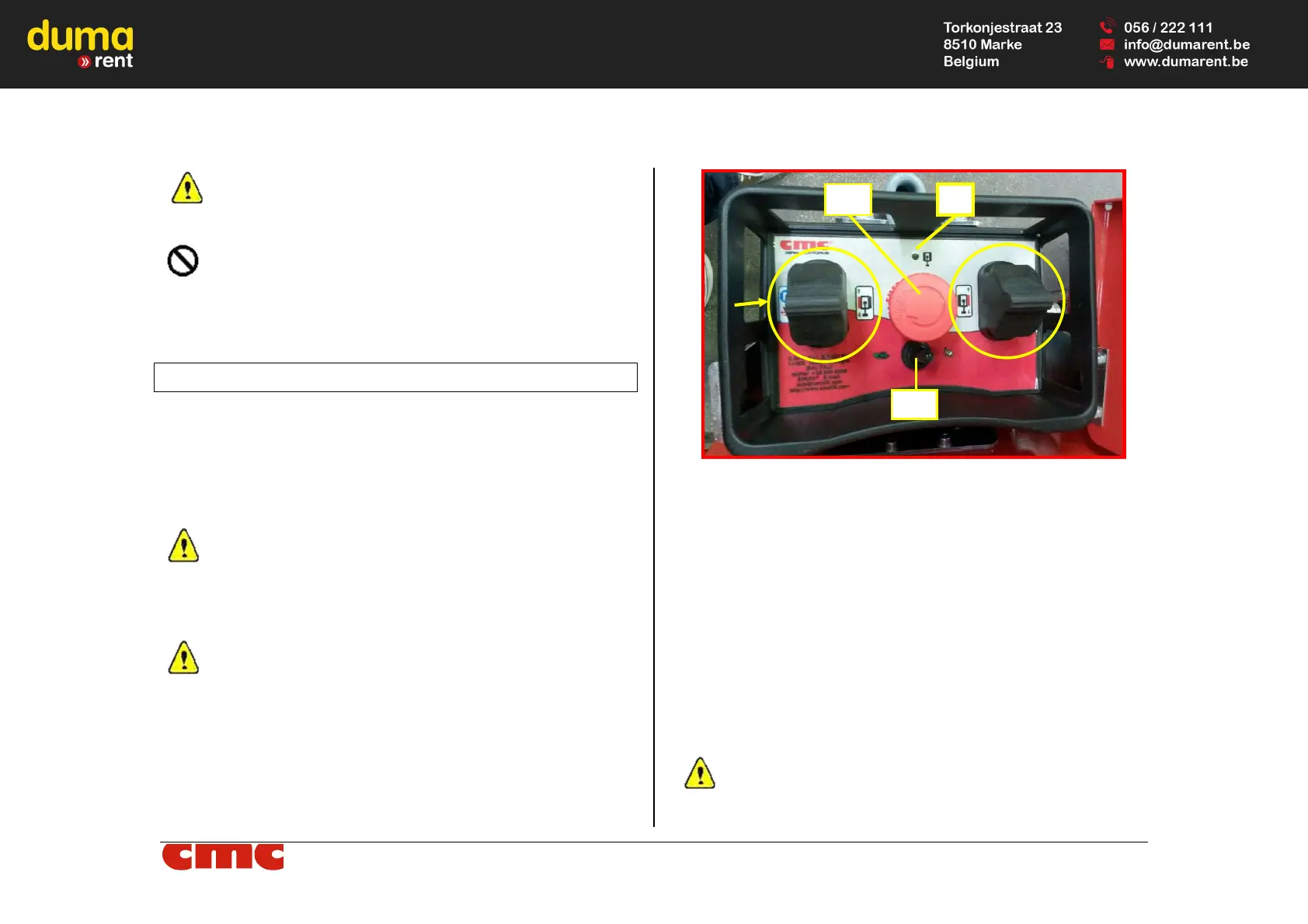
The travel of the machine can be performed by using the wired remote con-
trol, usable on the ground (the activation of this directly excludes the use of
the basket control station), which has:
Picture 5: wired remote control for MEWP travel.
• left track joystick J1 (Picture 5):
- pushing the joystick forward, the travel of the left track forward is
obtained;
- pushing the joystick backwards, the travel of the left track back-
ward is performed.
• right track joystick J2 (Picture 5):
- pushing the joystick forward, travel of the right track forward is ob-
tained;
- pushing the joystick backwards, the travel of the right track back-
ward is performed.
• EB emergency button (Picture 5): red and mushroom-shaped, it blocks
the machine by removing the power supply to the control circuits. This
switch has priority over any other command: it makes possible only the
manual emergency lowering of the machine on the ground.
The emergency button has an auto-detent mechanical locking
system; therefore, it is necessary to unlock the button turning it
clockwise to reset its operability.
J1
J2