MAN.161 Rev.7 ENG - Use and maintenance manual S15 page
19
of
71
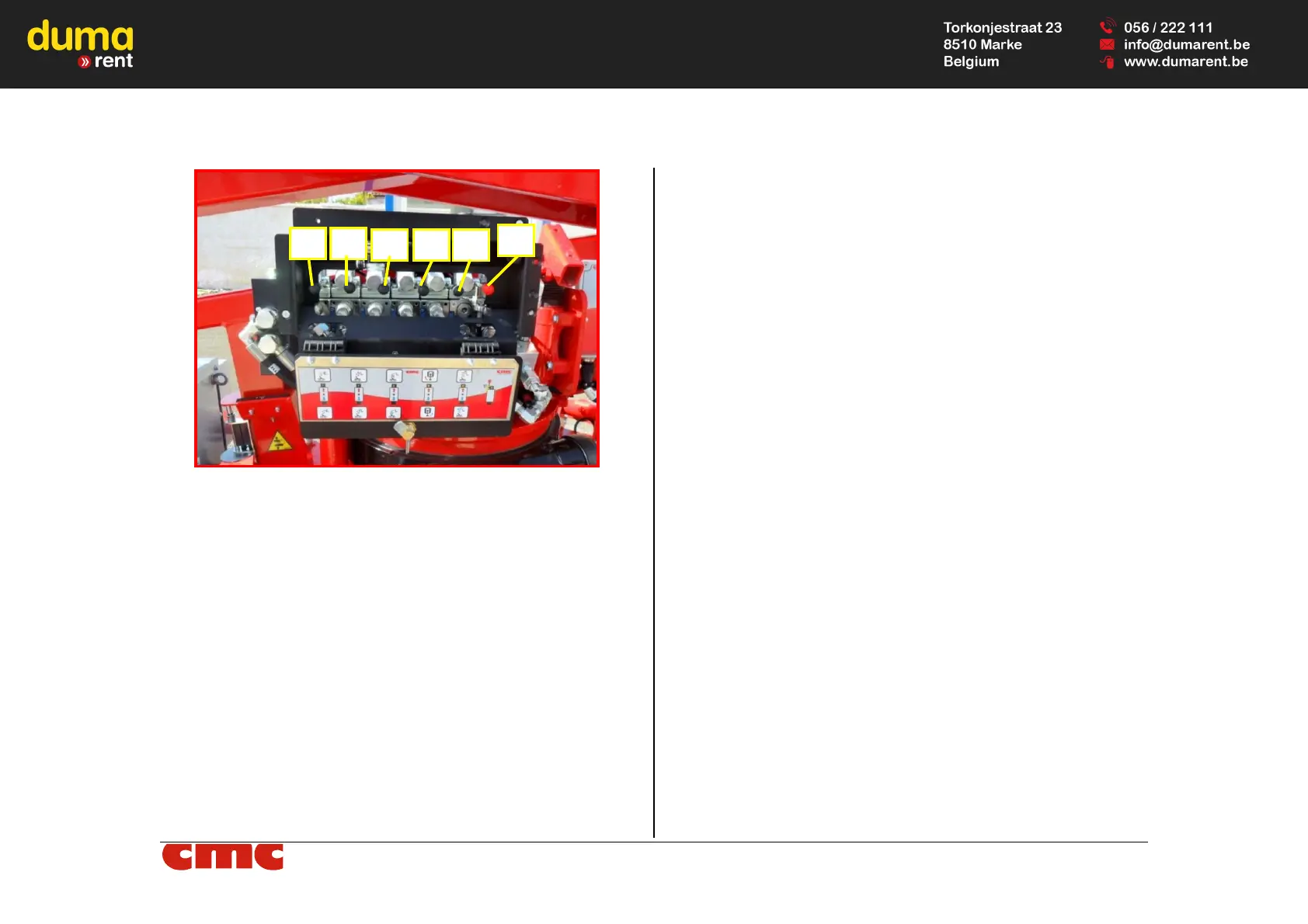
Picture 11: emergency control station.
It is formed by:
- proportional lever 1 (Picture 11): it is activated simultaneously with
the other manoeuvres;
- lever 2 for lifting/lowering of the jib (Picture 11): it produces the
lifting (lever at the top) and the descent (lever at the bottom) of the
jib;
- lever 3 for lifting/lowering of the boom (Picture 11): it carries out
the lifting (lever at the top) and the descent (lever at the bottom) of
the boom;
- lever 4 for lifting/lowering of the pantograph (Picture 11): it pro-
duces the lifting (lever at the top) and the descent (lever at the bot-
tom) of the pantograph;
- lever 5 for turret rotation (Picture 11): it activates the clockwise
rotation (lever at the top) and the counterclockwise rotation (lever at
the bottom) of the turret.
- lever 6 for extension/retraction of the boom (Picture 11): it acti-
vates the extension (lever at the top) and the retraction (lever at the
bottom) of the boom.