Installation of the dual-antenna mode
98-141779-G Appendix B: Antenna Diversity Solution (ADS) B-3
BBBB
System overview
A Master ACU and a Slave ACU are defined in the system. The modem is connected to and
configured as modem in the Master ACU. The Slave ACU is configured as a slave unit by
selecting the Master antenna as modem. The satellite information is communicated by the
modem to the Master ACU through an Ethernet cable. The BUC M&C is communicated by
the modem to the Master ACU through a standard serial cable. The BUC Key Line is
controlled by the modem through a key-line splitter cable from the modem to each ACU
(Master & Slave).
The switching from one antenna to the other is handled by the Master ACU based on
several criteria, like predefined blocking zones, unexpected blocking or antenna state. In
case the active antenna enters a blocking zone or is blocked by f.ex. a crane, the Master
ACU commands the idle antenna of the dual antenna system to take over and the system
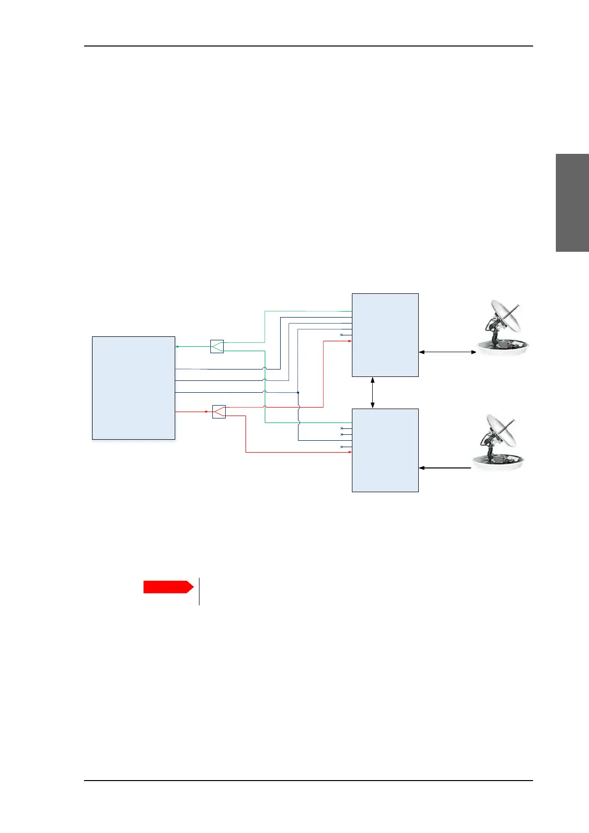
continues to provide network access. A connection diagram is shown in the following
figure.
Installation
To install the dual antennas, do as follows:
1. Install the Master ADU, ACU, the RX combiner and the modem as shown in Figure B-
2: ADS connection diagram.
2. Install the Slave ADU, ACU, the TX splitter as shown in Figure B-2: ADS connection
diagram.
3. Provide the vessel heading in the web interface of the Master ACU and Slave ACU, see
NMEA 0183 connector on page 4-3.
4. Connect the cables as shown in Figure B-2: ADS connection diagram and in the
following table.
Figure B-2: ADS connection diagram
ADU (Slave)
ADU (Master)
Modem
ACU
(Master)
ACU
(Slave)
LAN
RX (L-Band)
TX (L-Band)
BUC M&C (RS-232)
ACU M&C (Ethernet)
Keyline (RS-422)
RX (L-Band)
RX (L-Band)
TX (L-Band)
TX (L-Band)
BUC M&C (RS-232)
ACU M&C (Ethernet)
Keyline (RS-422)
Keyline (RS-422)
TX Splitter
RX combiner
Do not power on the modem; the modem must only be turned on when the
complete system is ready to perform a One Touch Commissioning (OTC).

 Loading...


