Installation of the dual-antenna mode
B-4 Appendix B: Antenna Diversity Solution (ADS) 98-141779-G
LAN setup and cabling
1. In GX ADS, bridge LAN1, LAN3 and LAN4 on master and slave.
2. Access the Master ACU on LAN port 1,3 & 4, IP:192.168.1.2
3. Access the Slave ACU on LAN port 1, 3 & 4 ip:192.168.1.102.
4. Connect the management device to LAN3 on slave. See Figure 3 GX ADS LAN cabling.
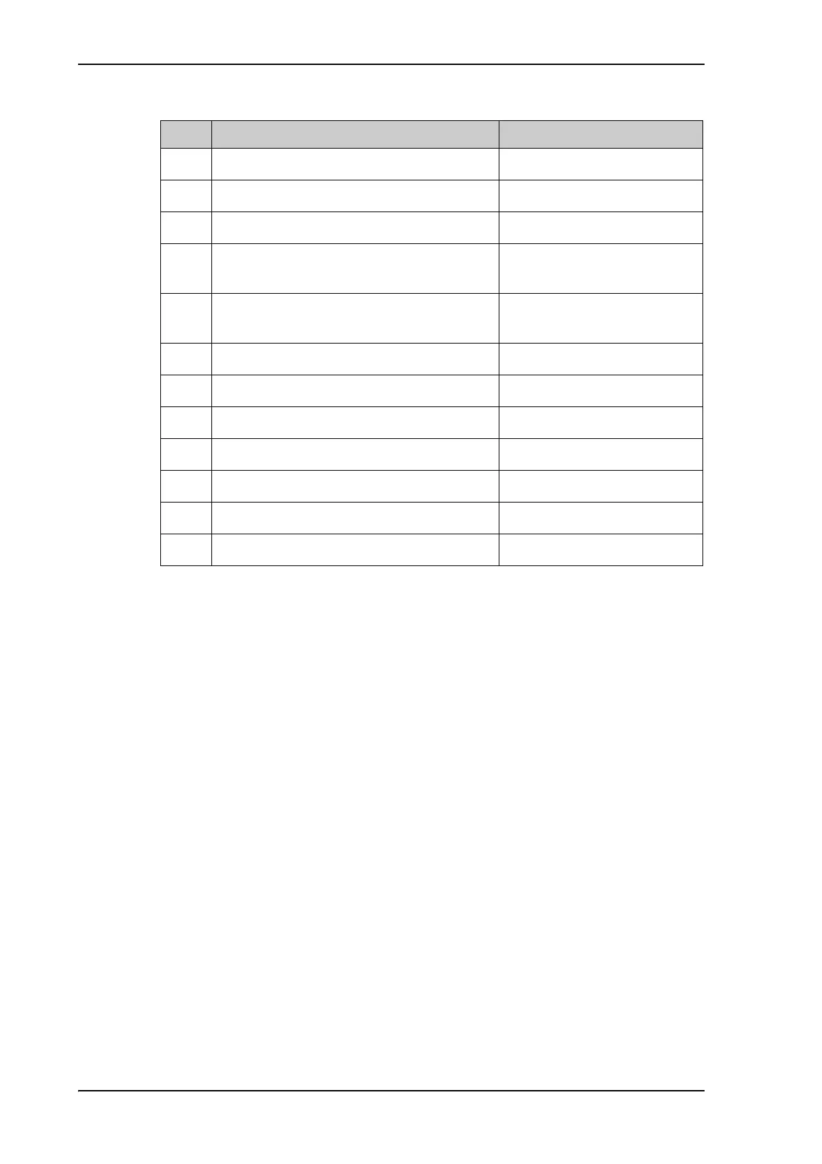
Cable. Connect cables GX specific Purpose
1
GMU LAN Port 1 to Master ACU LAN port 1 Modem M&C connection
2 Master ACU LAN Port 2 to Cisco router Inmarsat payload
3 Master ACU LAN Port 3 to Cisco router Inmarsat payload
4 Master ACU LAN 4 to Slave ACU LAN1 Master/slave/GMU
management
5 GMU Keyline to both ACUs RS422 (Cable
order number 37-159192)
Provide keyline signal to both
ACUs
6 Master ACU RS232 to GMU RS232 BUC M&C
7 Master ACU Rx Out to Rx combiner input 1 Rx when Master is active
8 Slave ACU Rx Out to Rx combiner input 2 Rx when Slave is active
9 Rx combiner output to GMU Rx 1 Rx to GMU
10 Master ACU Tx In to Tx splitter output 1 Enabled when Master is active
11 Slave ACU Tx In to Tx splitter output 2 Enabled when Slave is active
12 Tx splitter input to GMU Tx out Tx from GMU
Table B-1: GX ADS, dual mode antenna, cabling

 Loading...


