Signal Processor and Power Supply Units
To mount the signal processor first remove the cover by loosening the four
captive screws, unplug the ribbon cable at the connector on the lid PCB. The
case is then secured to a firm support by use of the four mounting holes found
in the four corners of the case, outside the sealing rim. Since the mounting
holes are located outside the seal of the case, it is not necessary to seal the
mounting holes after installation, nor is it necessary to remove the circuitry from
the case for installation.
If commissioning is not to be carried out immediately, reattach the lid to the
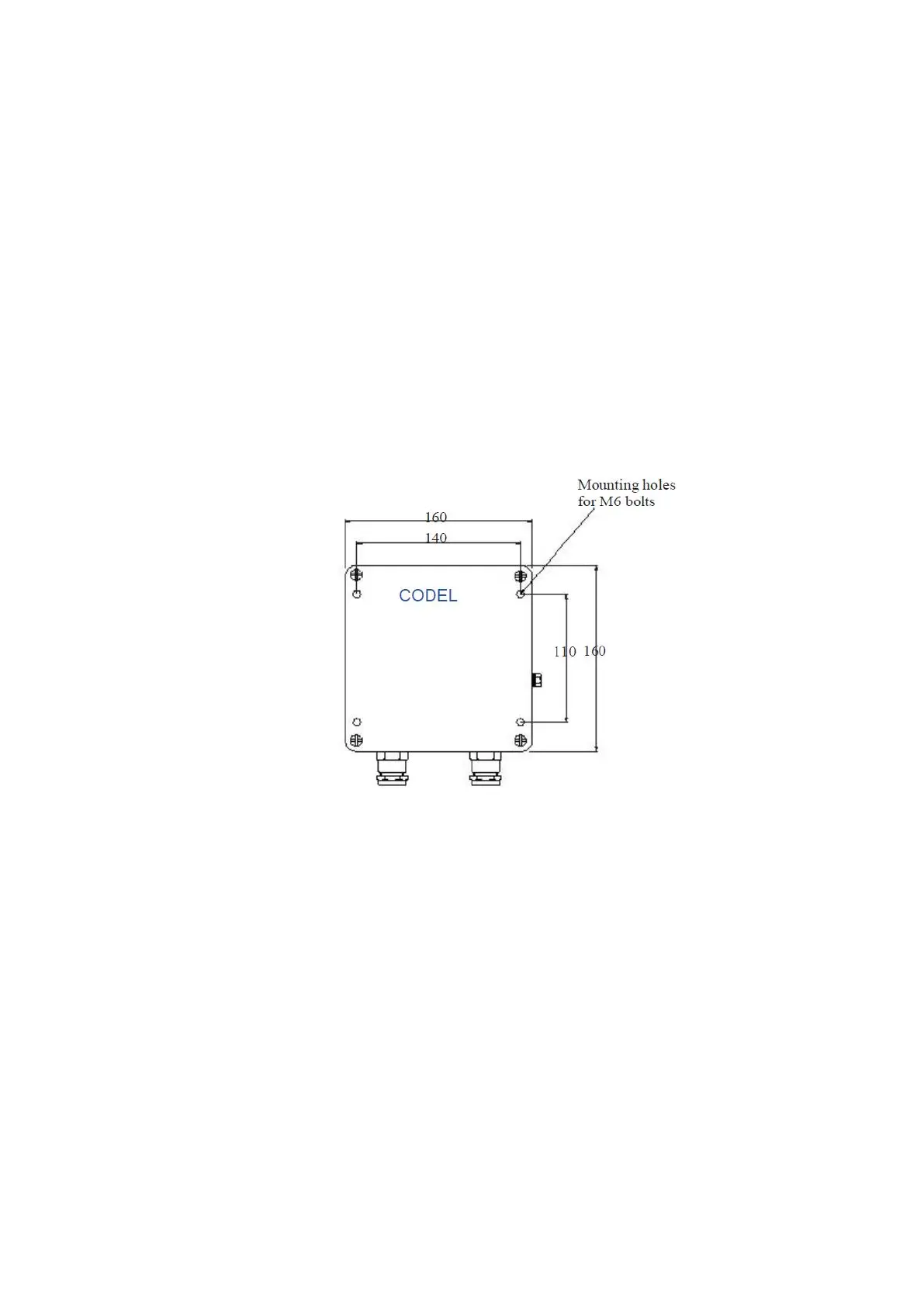
processor. Dimensions and mounting details are shown in Figure 5.
Installation of the power supply unit is carried out similar to the above.
Figure 5 : Signal Processor/Power Supply Mounting Details
AC Supplies
The instrument may be powered from an AC supply (50 or 60Hz) at voltages
ranging from 88V to 264V. No voltage selection is necessary.
! When connecting the cores of the mains cable into the power
supply unit, ensure that the cable is disconnected from the
mains power supply.