Calibrate
From this option the levels of the detector within the receiver and within the
transmitter may be displayed. The basic calibration of the instrument is set by a
‘Gain Factor’ which can be calculated during a calibration routine.
Press the ENTER key while this is displayed and the following options are
available :
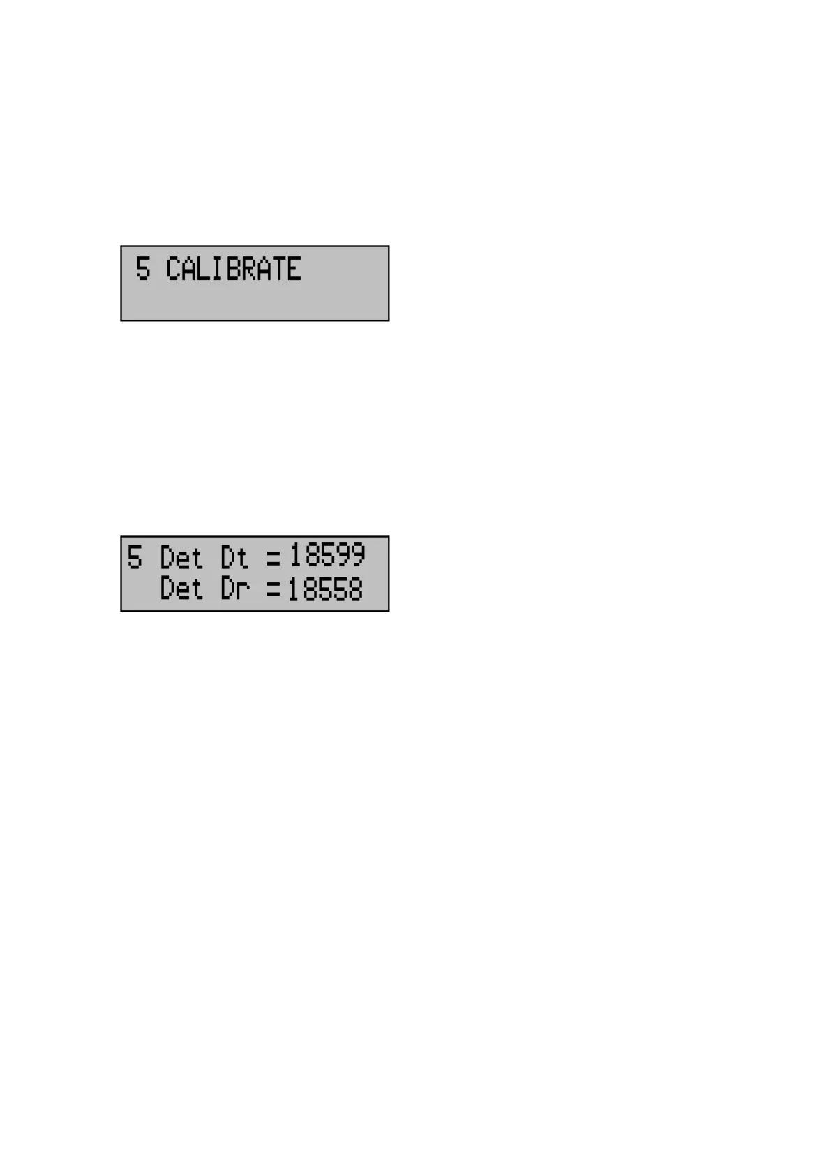
Set Detectors
Dt is the level from the detector within the transmitter, and Dr is the level from
within the receiver. Fault conditions are displayed for each detector. Once
aligned correctly increase receiver gain until the fault condition 'Rx saturated is
displayed', then decrease receiver gain by one.
! If the receiver signal is extremely high, saturation of the
analogue to digital converter (ADC) within the processor may
occur. As a result the fault condition 'Rx saturated' is displayed.
If this fault should appear, then the receiver Gain should be
reduced accordingly.