Technical Manual Page 13 CODEL
OPS.080 Issue : C Rev. : Date : 16/7/08 Doc. i/d : 0080/6 Ref. : 080040
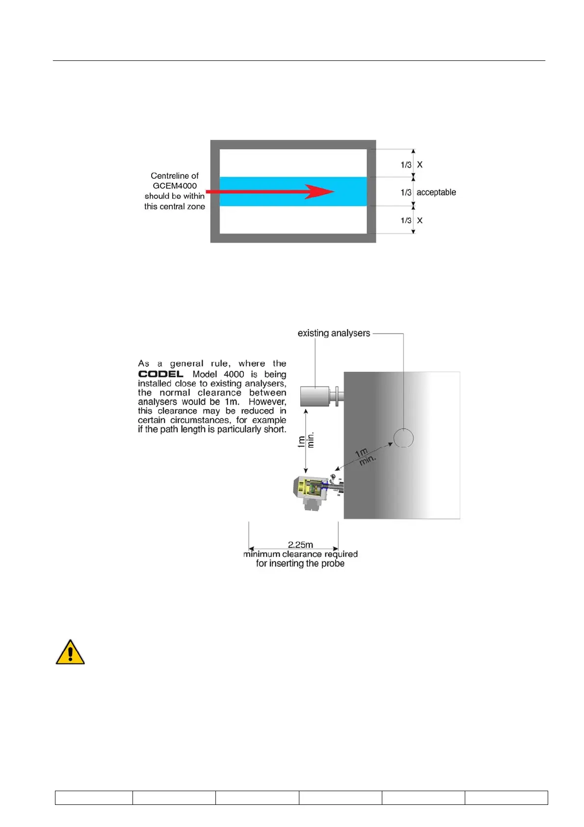
The measurement tube should always be on the centre line of circular ducts. On square or rectangular ducts,
the axis may be displaced from the centre line. Figure 8 shows the recommended displacement limit.
Figure 8 : Rectangular Ducts - Acceptable Position
In many applications, the GCEM4000 analyser will be installed in close proximity to other analysers. Figure 9
shows the minimum separation required.
Figure 9 : Spacing From Other Analysers
4.3. Fitting of Stub-Pipes and Mounting Flanges
Before proceeding further note that under no circumstances should holes be cut in the stack
with the plant operational if flue gases are under positive pressure with respect to atmosphere.
Even if pressure is believed to be negative great care should be exercised and all appropriate
protective clothing, including eye protection, should be worn.
Construct a mounting assembly (Figure 10) by welding a stainless steel mounting-flange (BS 4504 PN16
DN200) to a suitable diameter stub-pipe. This should be 8" nominal bore stainless steel tube and long enough to
extend about 200mm outside the outer surface (including lagging) of the duct or stack, where possible.
Cut 'slip-fit' holes in the duct at the chosen position; note that the assembly should be installed at a 5
0
downward
angle to the horizontal to allow condensate to flow into the stack.