Technical Manual Page 23 CODEL
OPS.080 Issue : C Rev. : Date : 16/7/08 Doc. i/d : 0080/6 Ref. : 080040
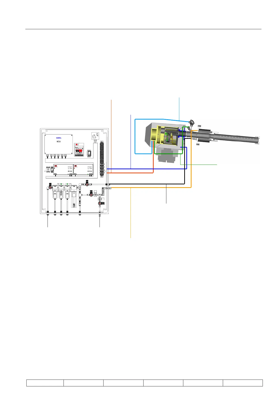
4.10. System Connections
All pipes, tubing and cables between the GCEM4000 sensor head, GCU, active weather cover and probe are
supplied by CODEL and are illustrated below.
Figure 15 : System Connections
Note that the GCU shown is for illustration purposes only and will vary project-to-project – please refer to
contract-specific drawings for terminal numbers.
The pressure, thermocouple and sensor head cables are connected as shown below. Remember that these
cables should pass through the front [plate of the weather cover – for full details refer to Section 4.6. Fitting the
Active Weather Cover and Sensor Head.
Thermocouple
8-Core CODEL local bus
(+48V, MOSI, MISO & 0V,
O2 Input & Weather Cover
Temperature)
Weather Cover
Power Supply
Zero Span Gas Supply
(20 litre/min during Cals)
Dead Zone Supply
(constant purge 5 litre/min)
Pressure
Span Gas IN Compressed Air IN